39
5 Planning the installation
Planning the grid connection (AC)
Installation and Operation Manual M50A_260 RPI503M260000 Product version L and M EU V1.3 EN 2023-08-14
5.4.7 Permissible grid voltages
3P3W Voltage Range 3P4W Voltage Range
L1-L2
400 V
AC
-20%/+30% L1-N 230 V
AC
-20%/+30%
L1-L3
400 V
AC
-20%/+30% L2-N 230 V
AC
-20%/+30%
L2-L3
400 V
AC
-20%/+30% L3-N 230 V
AC
-20%/+30%
5.4.8 Selecting the AC cable
5.4.8.1 Technical properties of the AC terminal block
Connection type Screws with hexagon socket head
Rated current I
N
96 A
Rated voltage U
N
1000 V
Type of attachment
● 4.5 mm hexagon socket (L1,
L2, L3, N)
● M8 nut (PE)
Tightening torque
● 12.4 Nm (L1, L2, L3, N)
● 14.7 Nm (PE)
Table 5.1.: Technical specication for the AC terminal block
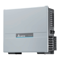
180 mm
Fig. 5.17: Free space for wiring on the AC terminal block
5.4.8.2 Notes on calculating the cable cross-section
► Consider the following factors when calculating the cable
cross-section:
– Cable material
– Temperature conditions
– Cable length
– Installation type
– Voltage drop
– Loss of power in the cable
► Always follow the IEC 60364-5-52 requirements and your
country-specic installation instructions.
► France: Follow the installation instructions of UTE 15-712-
1. This standard contains the requirements for minimum
cable diameters and for avoiding overheating due to high
currents.
► Germany: Follow the installation instructions of VDE 0100-
712. This standard contains the requirements for minimum
cable diameters and for avoiding overheating due to high
currents.
5.4.8.3 Specications for copper AC cables
Min./max. Cable diameter 21,9 to 44,7 mm
Min./max. Wire cross section
Without wire end sleeve
● Rigid cable 25 to 60 mm
2
● Multi-wire cable 25 to 60 mm
2
With wire end sleeve
● Flexible cable 25 to 60 mm
2
Table 5.2.: Specications for copper AC cables
5.4.8.4 Specications for aluminum AC cables
Min./max. Cable diameter 21,9 to 44,7 mm
Min./max. Wire cross section
Without wire end sleeve
● round, single-wire (rs) 35 to 60 mm
2
● round, multi-wire (rm) 35 to 60 mm
2
● sector-shaped (ss)
1)
35 to 60 mm
2
1) Observe the installation instructions for the use of sector-shaped aluminum
cables (see section 5.4.8.7, p. 40)
Table 5.3.: Specications for aluminum AC cables
5.4.8.5 Stripping length
20 mm20 mm
Fig. 5.18: Stripping length for AC cables
5.4.8.6 Handling aluminum conductors during installation
work
► The special properties of aluminum must be taken into con-
sideration when using aluminum conductors:
– Aluminum "ows," i.e. it gives way under pressure.
– A thin non-conductive oxide layer forms within a few
minutes on de-insulation, which increases the contact
resistance between the conductor and clamping point.
– The specic conductivity and hence the current carry-
ing capacity is approximately one third less than that of
copper.
 Loading...