19
4 Product overview
DC-side components
Installation and Operation Manual M50A_260 RPI503M260000 Product version L and M EU V1.3 EN 2023-08-14
4.6 DC-side components
Related topics
“5.5 Planning the connection of the solar modules (DC)”, page
41
“7.9 Connecting the solar modules (DC)”, page 80
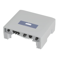
4.6.1 DC connector panel
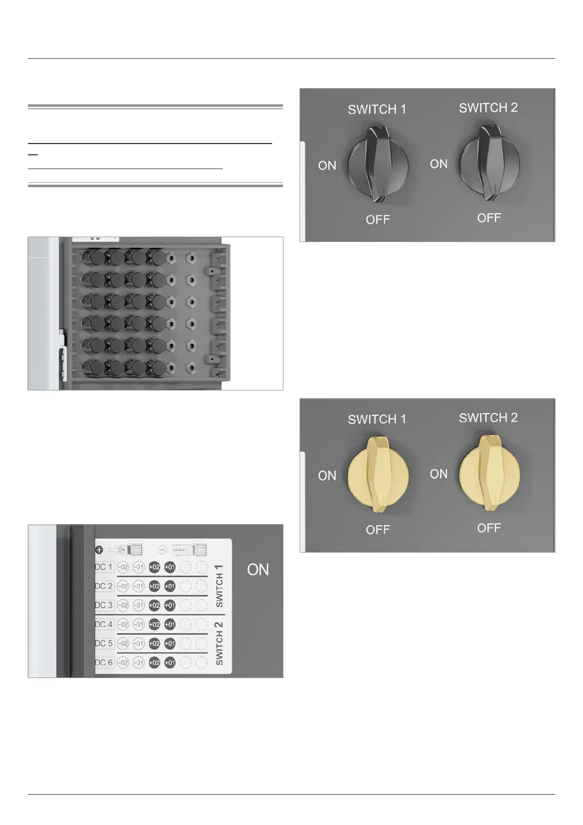
Fig. 4.6: DC connection panel
The DC connector panel has 12 pairs of DC connectors (6 MPP
trackers with 2 pairs of DC connectors each).
Plug type:
● DC+: Amphenol H4 for 4/6 mm
2
(Amphenol part number
H4CFC4D●MS)
● DC–: Amphenol H4 for 4/6 mm
2
(Amphenol part number
H4CMC4D●MS)
12 pairs of DC plugs are supplied in the scope of delivery.
Fig. 4.7: Label showing the assignment of each DC connector
The assignment of the individual DC connectors to the module
strings is shown on a label.
4.6.2 DC disconnectors
Fig. 4.8: DC disconnectors
The DC disconnectors are marked on the inverter with the words
SWITCH 1 and SWITCH 2.
DC disconnector 1 separates the DC strings of MPP trackers 1
to 3.
DC disconnector 2 separates the DC strings of MPP trackers 4
to 6.
Germany: The DC disconnectors meet the requirements of
VDE0100-712.
France: The DC disconnectors meet the requirements of
UTE 15-712-1.
Fig. 4.9: Both DC disconnectors in the OFF position = the
connection to the solar modules is disconnected
The connection between the inverter and the solar modules is
disconnected when both DC disconnectors are in the OFF posi-
tion.


 To Next Page