49
5 Planning the installation
Planning the device communication and plant monitoring
Installation and Operation Manual M50A_260 RPI503M260000 Product version L and M EU V1.3 EN 2023-08-14
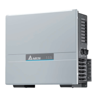
5.7.8 Connecting a ripple control receiver
Fig. 5.29: Terminal block with digital inputs
An external ripple control receiver can be connected to the digital
inputs.
The digital inputs are located on the communication card.
Pin Naming Short cir-
cuit
Assigned action
1 V1 - -
2 K0 V1 + K0 External power-o (EPO)
3 K1 V1 + K1
Maximum active power lim-
ited to 0 %
4 K2 V1 + K2
Maximum active power lim-
ited to 30 %
5 K3 V1 + K3
Maximum active power lim-
ited to 60 %
6 K4 V1 + K4
Maximum active power lim-
ited to 100%
7 K5 V1 + K5 Reserved
8 K6 V1 + K6 Reserved
Table 5.7.: Pin assignment of the terminal block with digital inputs
for connecting a ripple control receiver
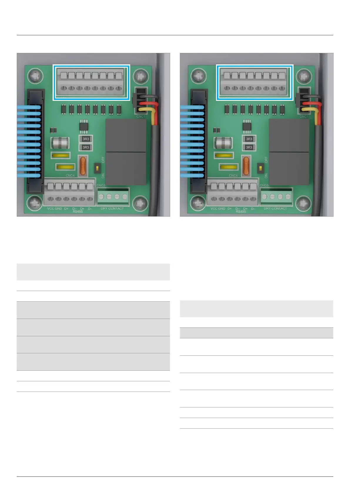
5.7.9 External power-o
Fig. 5.30: Terminal block with digital inputs
To disconnect the inverter AC-side from the grid connection point,
a switching signal can be sent via an external monitoring unit
using the digital input K0.
The relay is designed at the factory as a normally open contact.
The relay can also be set as an normally closed contact in the
inverter settings.
The connection for external disconnection is located on the termi-
nal block with the digital inputs of the communication card.
Pin Naming Short cir-
cuit
Assigned action
1 V1 - -
2 K0 V1 + K0 External power-o (EPO)
3 K1 V1 + K1
Maximum active power lim-
ited to 0%
4 K2 V1 + K2
Maximum active power lim-
ited to 30%
5 K3 V1 + K3
Maximum active power lim-
ited to 60%
6 K4 V1 + K4
Maximum active power lim-
ited to 100%
7 K5 V1 + K5 Reserved
8 K6 V1 + K6 Reserved
Table 5.8.: Pin assignment of the terminal block for the external
power-o
 Loading...