23
4 Product overview
Cooling system
Installation and Operation Manual M50A_260 RPI503M260000 Product version L and M EU V1.3 EN 2023-08-14
4.9 Cooling system
Related topics
“5.1 Installation location”, page 29
“11.5 Cleaning/replacing the fan module”, page 109
“11.6 Cleaning the air outlets”, page 113
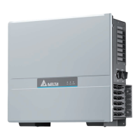
4.9.1 Air inlet, air outlet and fan module
Fig. 4.17: Air inlet with fan module on the left side
Fig. 4.18: Air outlet on the right side
The air for cooling is drawn in through the air inlet on the left side
of the inverter. The heated air is released back to the environ-
ment through the air outlets on the right side of the inverter.
The fan module can be replaced.
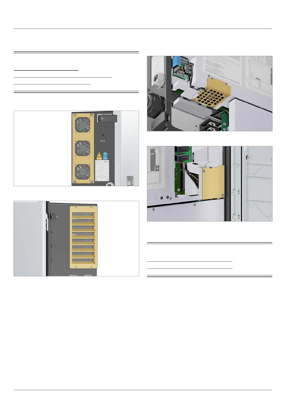
4.9.2 Internal fans
The internal fans circulate the air inside the inverter to prevent
heat buildup.
Fig. 4.19: Internal fan 1
Fig. 4.20: Internal fan 2
Related topics
“11.3 Clean/replace internal fan 1”, page 100
“11.4 Clean/replace internal fan 2”, page 104
 Loading...


