63
7 Installation
Connecting the communication card
Installation and Operation Manual M50A_260 RPI503M260000 Product version L and M EU V1.3 EN 2023-08-14
7.7 Connecting the communication card
The connections for RS485, the dry contacts, the
digital inputs and the external power-o (EPO)
are all on the communication card. This means
that the installation work can be combined.
NOTICE
Water ingress.
► All sealing caps removed during installa-
tion should be stored for later use (e.g. (e.g.
transportation or storage).
7.7.1 Connections on the communication card
5 4
1
3
2
6
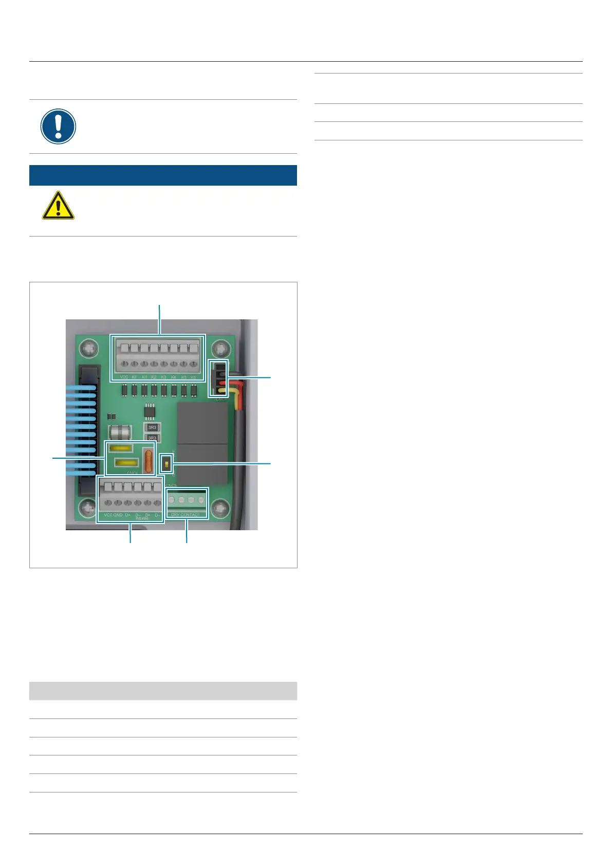
Fig. 7.2: Components of the communication card
1 Digital inputs and external power-o (terminal block)
2 Power supply for internal fan 1
2 DIP switch for the RS485 termination resistor
3 2 x dry contacts (terminal block)
4 RS485 (terminal block)
5 Protection against electromagnetic interference (EMI)
Connection Connection type
2x RS485 (DATA+ and DATA–) Terminal block
1x VCC (12 V, 0.5 A) Terminal block
6x digital inputs Terminal block
2x dry contacts Terminal block
1x external power-o (EPO) Terminal block
Table 7.2.: Connections on the communication card
Cable type
Shielded and twisted pair cable
(CAT5 or CAT6)
Cable diameter
2 x 7.2 / 8 / 10 mm
Wire cross section 0.25 ... 1.5 mm
2
Table 7.3.: Specication of the communication cable
The communication cable is required for connection to the follow-
ing units:
● Data logger
● External alarm unit
● Ripple control receiver
● External power-o
Lay the communication cable with a suitable clearance to the AC
and DC cables to prevent interference in the data connection.