5 Planning the installation
Planning the device communication and plant monitoring
46
Installation and Operation Manual M50A_260 RPI503M260000 Product version L and M EU V1.3 EN 2023-08-14
5.7.3 Communication cable requirements
Cable type
Shielded and twisted pair cable
(CAT5 or CAT6)
Cable diameter
7.2 / 8 / 10 mm
Wire cross section 0.25 to 1.5 mm
2
Table 5.5.: Specication of the communication cable
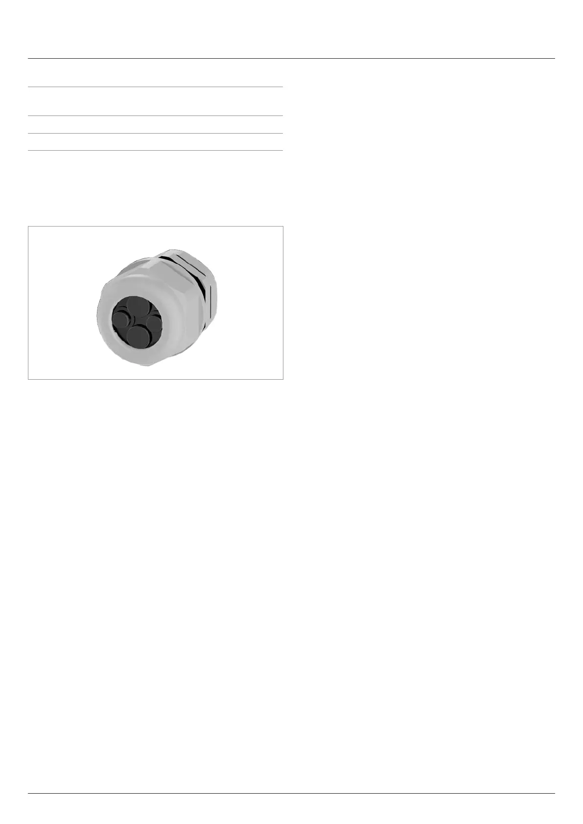
5.7.4 Cable gland for the communication con-
nection
The inverter has one cable gland for up to four communication
cables.
5.7.5 Connection of a data logger via RS485
The inverter can be connected to a data logger via RS485, e.g.
for monitoring the PV system or changing the inverter settings.
The SUNSPEC protocol with Modbus RTU is used for data trans-
mission.
Multiple inverters can be connected in series to a data logger.
Take into account the notes for ensuring a stable data connec-
tion.
Connecting a single inverter to a data logger
► Switch on the RS485 termination resistor.
► Lay the communication cable with a suitable clearance to
the AC and DC cables to prevent interference in the data
connection.
Connecting multiple inverters to a data logger
Consideration of the position of the data logger in the RS485 bus:
► The data logger is located at one of the two ends of the
RS485 bus:
– Switch the RS485 termination resistor of the data
logger on.
– Switch the RS485 termination resistor of the inverter at
the other end of the RS485 bus on.
► The data logger is not at either end of the RS485 bus:
– Switch the RS485 termination resistor of the data
logger o.
– Switch the RS485 termination resistor of the two invert-
ers at the ends of the RS485 bus on.
► Switch the RS485 termination resistor on all other inverters
o (default setting from the factory).
Further notes:
► Set a dierent inverter ID for each inverter. Otherwise the
data logger cannot identify the individual inverters.
► Set the same RS485 baud rate at each inverter (factory
setting: 19200).
► Lay the RS485 cable with a suitable clearance to the AC
and DC cables to prevent interference in the data connec-
tion.