5 Planning the installation
Planning the device communication and plant monitoring
48
Installation and Operation Manual M50A_260 RPI503M260000 Product version L and M EU V1.3 EN 2023-08-14
Connection via Wi-Fi
To use the Wi-Fi feature, the Wi-Fi module must be installed on
the inverter. The Wi-Fi module must be ordered separately from
Delta.
Connection via Sub-1G
The inverter is supplied with a Sub-1G antenna. You can order a
separate Sub-1G module for the DC1.
Required software
In order to access the DC1 and the inverter through it, you also
need:
● A mobile device (smartphone, tablet) with the MyDeltaSolar
app
or
● A Windows PC running the Delta Service Software (DSS)
The MyDeltaSolar app is available for iOS and Android.
You can download the DSS at https://solarsolutions.delta-emea.
com
.
5.7.7 Connecting an external alarm unit
The inverter has two relays for triggering external alarm devices.
The communication card contains 2 pairs of dry contacts, each of
which can be connected to an external acoustic or optical alarm
device.
The communication card also has a 12 V
DC
power supply.
Both relays are designed as normally open contacts.
After commissioning, each relay can be assigned an event at
which the relay switches. By default, the relays are disabled.
To set an event for the relays, you need:
● A mobile device (smartphone, tablet) with the MyDeltaSolar
app
or
● A Windows PC running the Delta Service Software (DSS)
The MyDeltaSolar app is available for iOS and Android.
You can download the DSS at https://solarsolutions.delta-emea.
com.
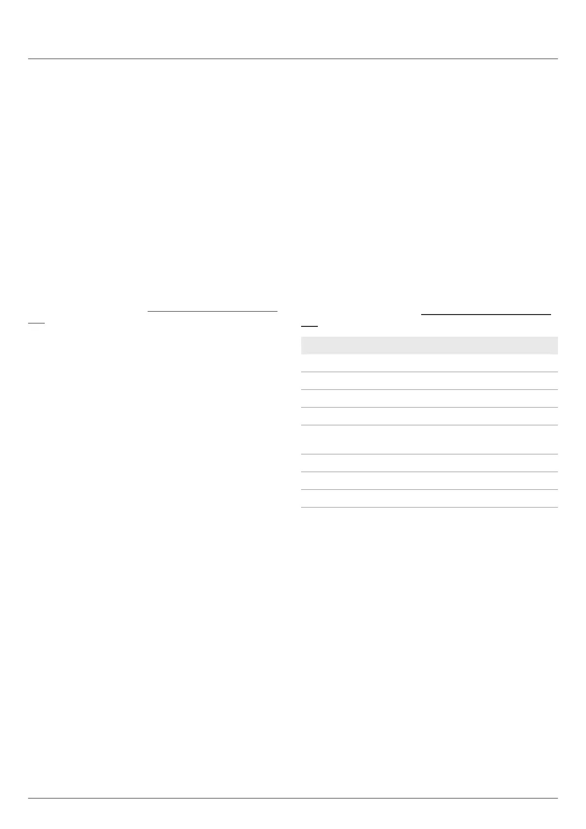
Event Description
Disabled
The function is disabled.
On Grid
The inverter is connected to the grid.
Fan defective
The fans are defective.
Insulation
The insulation test has failed.
Alarm
An error event message, fault message or
warning has been sent.
Error
An error event message has been sent.
Fault
A fault message has been sent.
Warning
A warning message has been sent.
Table 5.6.: Events for which the relay can trigger
The default setting for both relays is Disabled.
 Loading...