32
Installation and Operation Manual M50A_260 RPI503M260000 Product version L and M EU V1.3 EN 2023-08-14
5 Planning the installation
Installation location
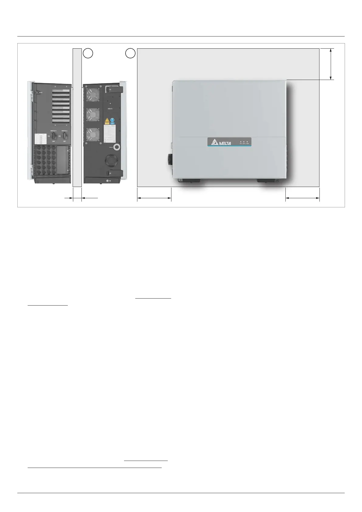
> 50 > 300 > 300
> 200
AA
and air circulation
Fig. 5.6: Mounting distances and air circulation, variant 3 (in mm)
► Ensure sucient air circulation. There must not be heat
buildup around the inverter. For installation clearances of
30 to 60 cm between two inverters, install a separation
plate (A) between the inverters. This separation plate is
designed to prevent the right-hand inverter from sucking in
the warm air of the left-hand inverter. No separation plate is
required for clearances greater than 60 cm.
► Observe Operating temperature range without derating
the Total operating temperature range (see “14. Technical
Data”, page 160).
When the operating temperature range without derating is
exceeded, the inverter reduces the AC power fed into the
grid.
When the Total operating temperature range is exceeded,
the inverter stops feeding AC power into the grid.
This is normal operating behavior for the inverter and is
necessary to protect the internal electronics.
► Position multiple inverters so that they do not heat each
other up.
► Observe the minimum bend radius of the cables used (es-
pecially the AC cable)!
► Ensure the accessibility of the side components (air lters,
fan module, AC cable gland, DC connector panel, etc.) for
maintenance and repair work.
► Allow space to the front to open the door.
► In areas with many trees or elds, pollen and other parts of
plants can clog the air inlets and air outlets, obstructing the
air ow.
If there is a loss of performance during operation, clogged
air lters may be a cause (see chapter “11. Replacing or
cleaning components, installing accessories”, page 97).