24
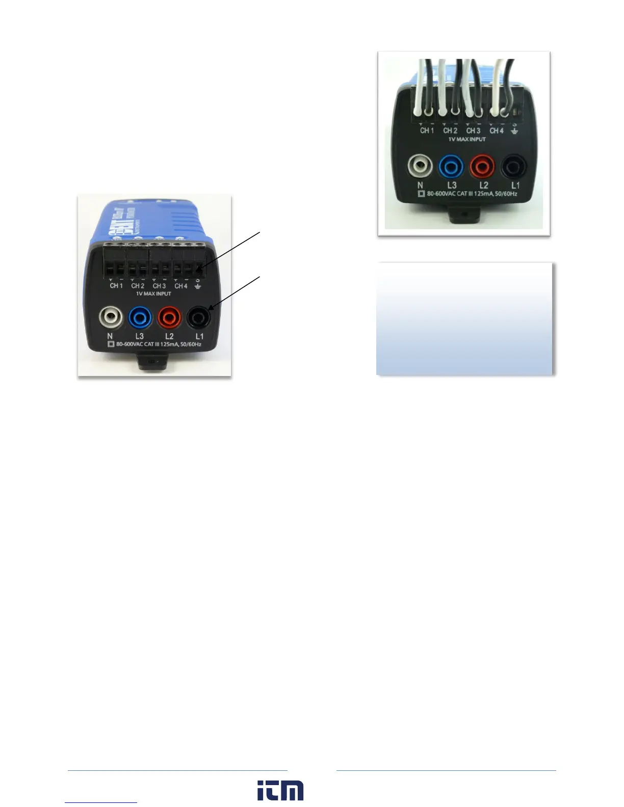
4) Connect the white wire on the CT to the positive terminal
o
n the measuring device.
5) Connect the black wire on the CT to the negative terminal
on the measuring device.
C
T 1 must be placed on the phase listed as V High for Channel 1 in the ELOG setup table. CT2, CT3 and
CT4 must also correspond to the appropriate phase as shown in Channels 2, 3, and 4 in the ELOG setup
table.
ID
OU
NOW
of a CT is required to ensure
proper measurement. If an arrow
is shown on the CT label, it should
be pointed toward the load.
Otherwise, use the instructions
printed on the CT.
Voltage lead
Current
Transformer
w ww. . com
information@itm.com1.800.561.8187