57
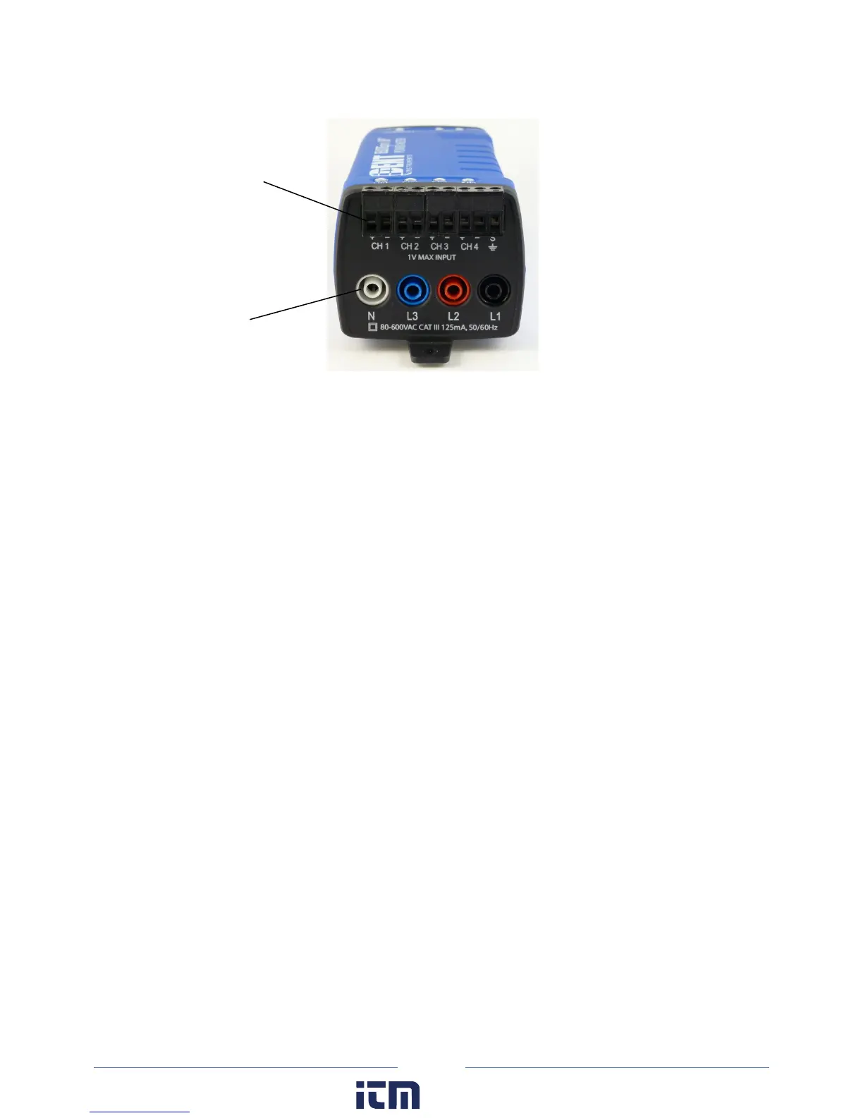
ELITEpro XC End View of CT and Voltage Lead Connections
2) Apply the CTs to the phases being monitored observing proper CT orientation.
3) If there is an arrow on the CT label, the label should point towards the load. Otherwise, use th
e
i
nstructions printed on the CT, for example: “This Side Toward Load.”
4) Connect the voltage leads to the different phases. Connect the Neutral wire first, then the remaining
v
oltage sense (phase) wires.
ELOG QUICK SETUP WIRING DIAGRAMS
When a Quick Setup is selected, the View Typical Setup button appears in the Quick Setup area of the
screen. Clicking this button displays a wiring diagram that corresponds to the selected setup, showing
how to connect the CTs and the voltage leads of the ELITEpro XC. The diagram can be printed and
carried into the field for easy reference during installation.
The following pages show the diagrams available for each Quick Setup.
w ww. . com
information@itm.com1.800.561.8187