45
Additionally, depending on the setup, Calculated Power Channels with configuration options display in
the lower section of the Setup Table screen. See Calculated Power Channels.
P
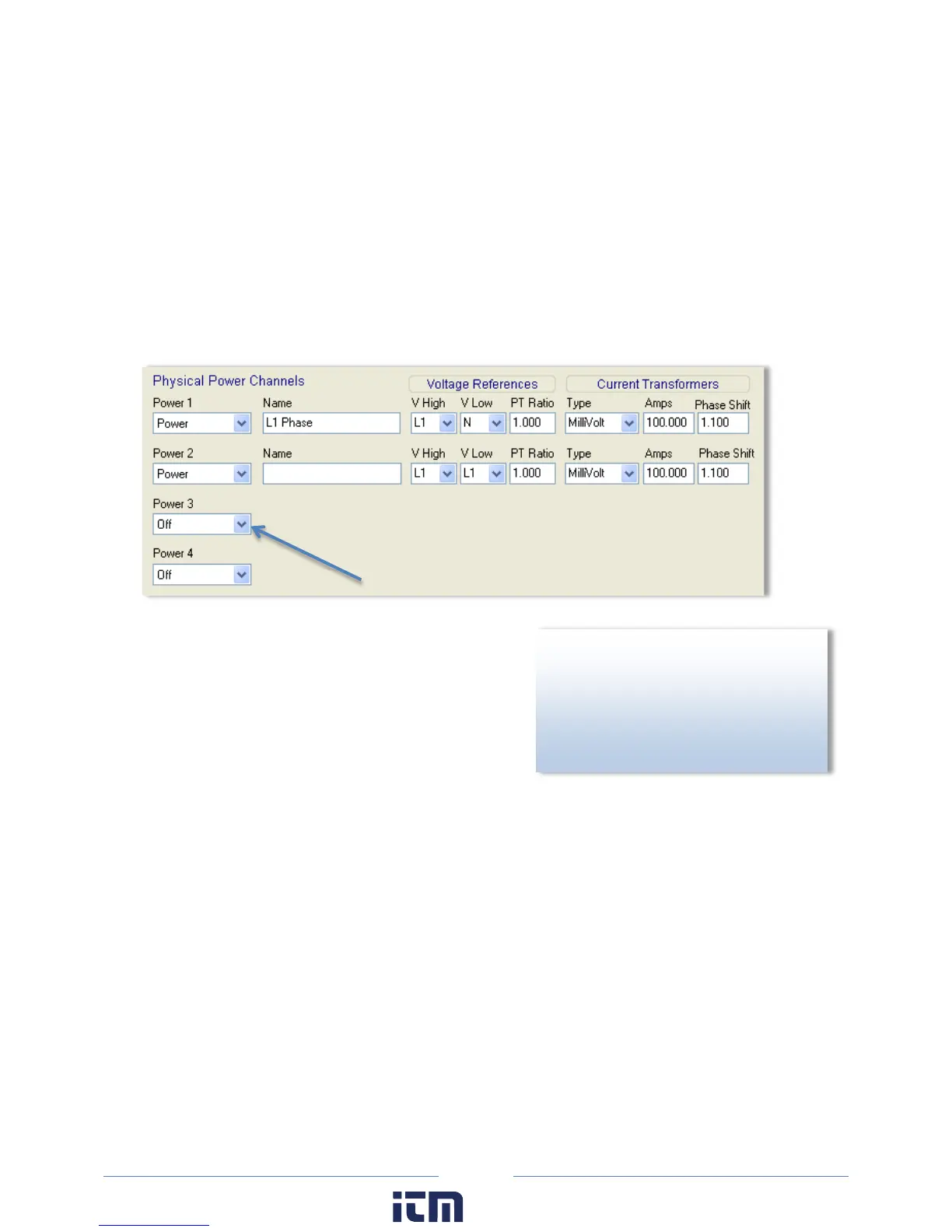
HYSICAL POWER CHANNELS
The ELITEpro XC has four configurable hardware channels corresponding to the current transformers or
other sensors.
1) Click on the maximize button in the upper right-hand corner of the Setup Table window to display as
much of the full screen as possible.
2) Click on the down arrow next to each channel you
want to configure.
CT 1 must be placed on the phase listed as V High for
Channel 1 in the ELOG setup table. CT2, CT3 and CT4
must also correspond to the appropriate phase as
shown in Channels 2, 3, and 4 in the ELOG setup table.
3) Select Power to turn on any channel. These channels
refer to the current transformer inputs from the ELITEpro XC. Selecting Power displays the options
for configuring the channel.
4) Enter a name for the channel, then select the Voltage References, Current Transformers, and any
Recorded Values.
N
OTE: The PT Ratio is used when monitoring voltages greater than 600 VAC (maximum rating of the
ELITEpro XC). Use an instrument grade transformer with low phase shift and high accuracy since errors
in the transformer will translate directly into errors in the recorded data. The PT Ratio value put into the
Setup Table in the logger should be the transformer primary:secondary ratio. This feature is useful when
monitoring high voltage loads such as found at a substation or on transmission lines.
For example, a potential transformer is used to monitor a 4160 VAC load. The transformer steps the
voltage down from 4160 to 120 VAC. The PT equals the transformer ratio or 4160/120 = 34.667. Thus,
34.667 would be used for the PT value in the channel Setup Table.
AUTION
Transformer) is not used on service
voltages greater than 600V, the
ELITEpro XC may overheat (or worse)
causing irreparable damage and
extreme danger to the user.
w ww. . com
information@itm.com1.800.561.8187