HI, MI, WI-700 service manual - 2 - component parts
2-2 Issue 9 04/2020
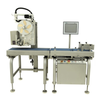
The electrical cabinet
The electrical cabinet for the 700 machine has several outlets around the cabinet for various parts of the
700 machine to be connected into.
These external connections are listed below.
Rear of cabinet
1 2 3 4
5 6 7
8
9
10
11
12
13
14
15
16
17 18 19 20
21
22
Cabinet right side
Cabinet left side
23
24 25
26
1 Infeed Motor
2 Scale Motor
3 Outfeed Motor
4 SubInfeed Motor
5 Infeed Sensor
6 Scale Sensor
7 Spare
8 Motor Switch - Infeed
9 Motor Switch - Outfeed (for
top & base m/c)
10 Motor Switch – Spare
(additional conveyor)
11 Motor Switch - Spare
(additional conveyor)
12 Outfeed motor driver (for
top & base m/c)
13 Power Lift – Labeller
14 Power Lift – Labeller
15 Air in - (to labeller)
16 Air in - (to labeller)
17 Labeller 1
18 Labeller 2
19 Spare
20 Mains In
21 Display
22 Load cell
23
Option outputs
E.g. outfeed pack sensor 1
& 2 (top labeller)
E.g. Outfeed conveyor mo-
tor cable
E.g. Ethernet communica-
tion to additional printer
24 External USB port
25 Communication to sleever
m/c
26 Base labeller applicator
 Loading...