Serial communications for the XBee/XBee-PRO RF Module
XBee / XBee-PRO RF Modules 802.15.4 Product Manual 20
• RF-received data frame
• Command response
• Event notifications such as reset, associate, disassociate, and so forth
The API provides alternative means of configuring modules and routing data at the host application
layer. A host application can send data frames to the module that contain address and payload
information instead of using command mode to modify addresses. The module will send data frames
to the application containing status packets; as well as source, RSSI and payload information from
received data packets.
The API operation option facilitates many operations such as the examples cited below:
• Transmitting data to multiple destinations without entering Command Mode
• Receive success/failure status of each transmitted RF packet
• Identify the source address of each received packet
To implement API operations, refer to API Operation for the XBee/XBee-PRO RF Module on page 89.
Flow control
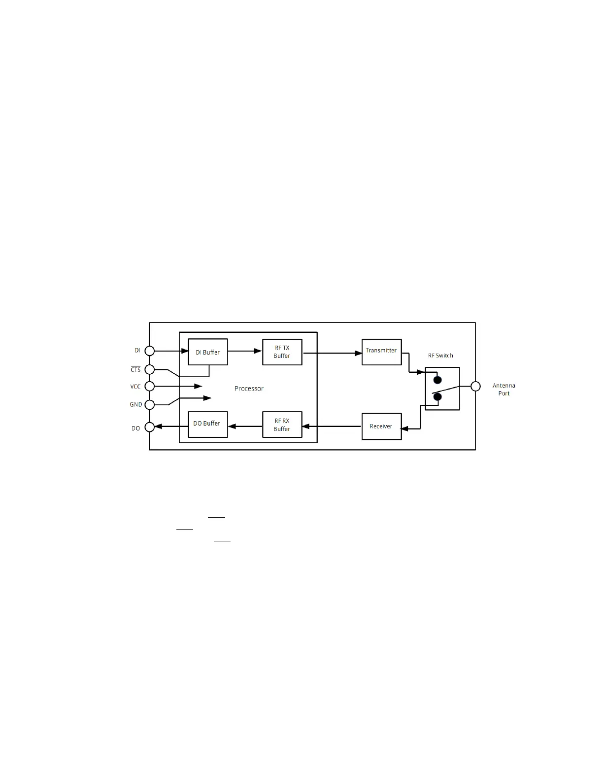
Figure 6: Internal data flow diagram
DI (Data In) buffer
When serial data enters the RF module through the DI pin (pin 3), the data is stored in the DI Buffer
until it can be processed.
Hardware Flow Control (CTS
). When the DI buffer is 17 bytes away from being full; by default, the
module de-asserts CTS
(high) to signal to the host device to stop sending data [refer to D7 (DIO7
Configuration) parameter]. CTS
is re-asserted after the DI Buffer has 34 bytes of memory available.
To eliminate the need for flow control:
1. Send messages that are smaller than the DI buffer size (202 bytes).
2. Interface at a lower baud rate [BD (Interface Data Rate) parameter] than the throughput data rate.
Case in which the DI Buffer may become full and possibly overflow:
If the module is receiving a continuous stream of RF data, any serial data that arrives on the DI pin is
placed in the DI Buffer. The data in the DI buffer will be transmitted over-the-air when the module is
no longer receiving RF data in the network.
Refer to the RO (Packetization Timeout), BD (Interface Data Rate) and D7 (DIO7 Configuration)
command descriptions for more information.