Pin signals for the XBee/XBee-PRO RF Module
XBee / XBee-PRO RF Modules 802.15.4 Product Manual 12
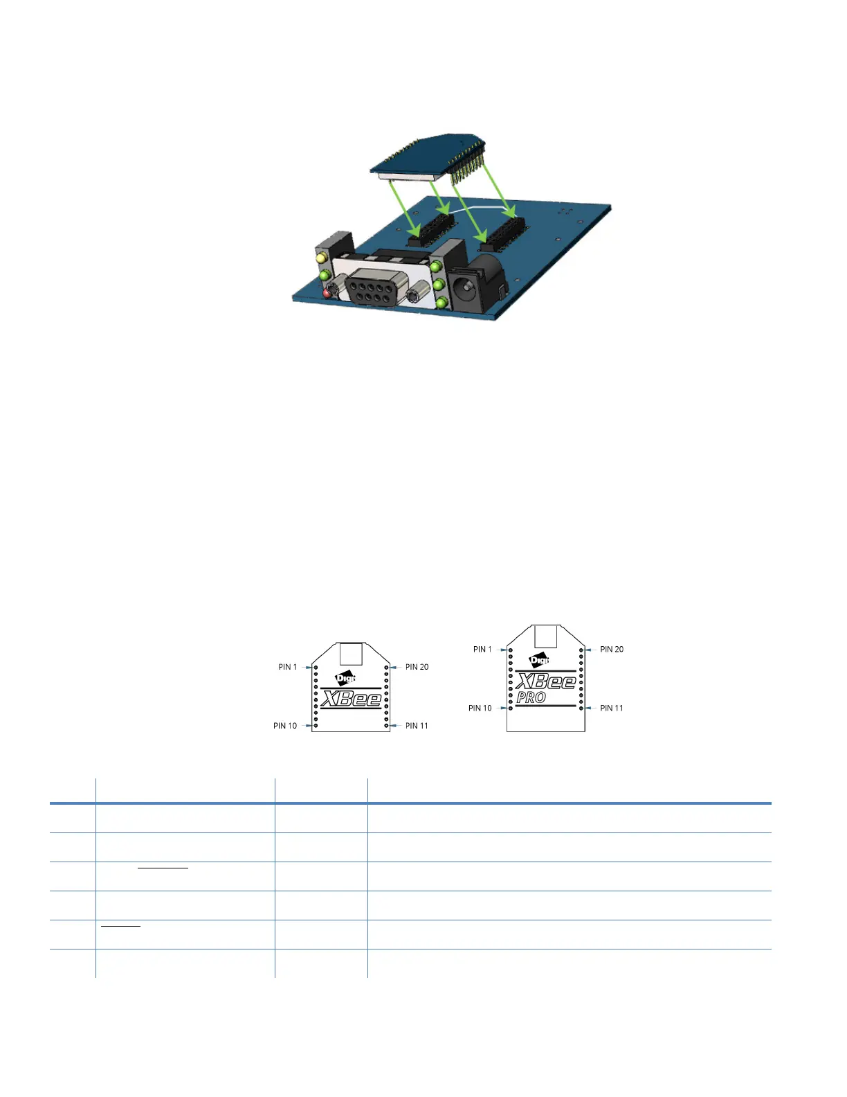
Figure 2: XBee-PRO Module mounting to an RS-232 interface board.
Century Interconnect manufactures the receptacles used on Digi development boards. Several other
manufacturers provide comparable mounting solutions, however, Digi currently uses the following
receptacles:
• Through-hole single-row receptacles -
Samtec P/N: MMS-110-01-L-SV (or equivalent)
• Surface-mount double-row receptacles -
Century Interconnect P/N: CPRMSL20-D-0-1 (or equivalent)
• Surface-mount single-row receptacles -
Samtec P/N: SMM-110-02-SM-S
We also recommend printing an outline of the module on the board to indicate the orientation the
module should be mounted.
Pin signals for the XBee/XBee-PRO RF Module
Figure 3: XBee / XBee-PRO RF Module pin number (top sides shown - shields are on the bottom)
Table 2: Pin assignments for the XBee-PRO Modules
(Low-asserted signals are distinguished with a horizontal line above signal name.)
Pin # Name Direction Description
1 VCC - Power supply
2 DOUT Output UART data out
3 DIN / CONFIG
Input UART data In
4 DO8* Either Digital output 8
5 RESET
Input Module reset (reset pulse must be at least 200 ns)
6 PWM0 / RSSI Either PWM output 0 / RX signal strength indicator