ADC and Digital I/O line support of the XBee/XBee-PRO RF module
XBee / XBee-PRO RF Modules 802.15.4 Product Manual 22
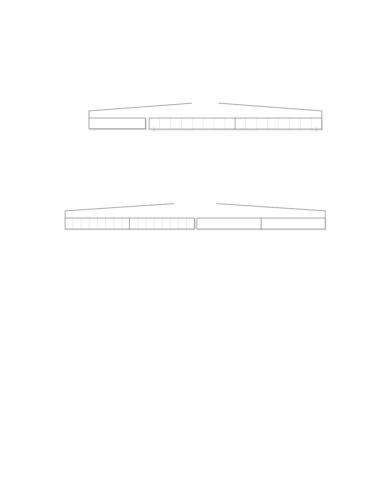
I/O data format
I/O data begins with a header. The first byte of the header defines the number of samples
forthcoming. The last two bytes of the header (Channel Indicator) define which inputs are active.
Each bit represents either a DIO line or ADC channel.
Figure 7: Header
Sample data follows the header and the channel indicator frame is used to determine how to read
the sample data. If any of the DIO lines are enabled, the first two bytes are the DIO sample. The ADC
data follows. ADC channel data is represented as an unsigned 10-bit value right-justified on a 16- bit
boundary.
Figure 8: Sample data
API support
I/O data is sent out the UART using an API frame. All other data can be sent and received using
Transparent Operation [refer to p19] or API framing if API mode is enabled (AP > 0).
API Operations support two RX (Receive) frame identifiers for I/O data (set 16-bit address to 0xFFFE
and the module will do 64-bit addressing):
• 0x82 for RX (Receive) Packet: 64-bit address I/O
• 0x83 for RX (Receive) Packet: 16-bit address I/O
The API command header is the same as shown in the RX (Receive) packet: 64-bit address on page 95
and RX (Receive) packet: 16-bit address IO on page 97 API types. RX data follows the format described
in I/O data format on page 22.
Applicable commands: AP (API Enable)
Sleep support
Automatic wakeup sampling can be suppressed by setting SO bit 1. When an RF module wakes, it will
always do a sample based on any active ADC or DIO lines. This allows sampling based on the sleep
cycle whether it be Cyclic Sleep (SM parameter = 4 or 5) or Pin Sleep (SM = 1 or 2). To gather more
samples when awake, set the IR (Sample Rate) parameter.
For Cyclic Sleep modes: If the IR parameter is set, the module will stay awake until the IT (Samples
before TX) parameter is met. The module will stay awake for ST (Time before Sleep) time.
Applicable commands: IR (Sample Rate), IT (Samples before TX), SM (Sleep Mode), IC (DIO Change
Detect), SO (Sleep Options)
Header
Bit set to ‘1’ if channel is active
Bytes 2 - 3 (Channel Indicator)
na D8A0A1A2A3A4A5 D7 D0D1D2D3D4D5D6
Byt e 1
Total number of samples
bit 15 bit 0
Sample Data
DIO Line Data is first (if enabled) ADC Line Data
ADCn MSB ADCn LSB7 0123456X 8XXXXXX