Design notes for the XBee/XBee-PRO RF Module
XBee / XBee-PRO RF Modules 802.15.4 Product Manual 13
Notes
• Minimum connections: VCC, GND, DOUT and DIN
• Minimum connections for updating firmware: VCC, GND, DIN, DOUT, RTS and DTR
• Signal direction is specified with respect to the module
• The module includes a 50 kpull-up resistor attached to RESET
• You can configure several of the input pull-ups using the PR command
• Leave any unused pins disconnected
Design notes for the XBee/XBee-PRO RF Module
The XBee modules do not specifically require any external circuitry or specific connections for proper
operation. However, there are some general design guidelines that are recommended for help in
troubleshooting and building a robust design.
Power supply design
Poor power supply can lead to poor radio performance, especially if the supply voltage is not kept
within tolerance or is excessively noisy. To help reduce noise, we recommend placing a 1.0 μF and 8.2
pF capacitor as near as possible to pin 1 on the XBee. If using a switching regulator for the power
supply, switching frequencies above 500 kHz are preferred. Power supply ripple should be limited to
a maximum 100 mV peak to peak.
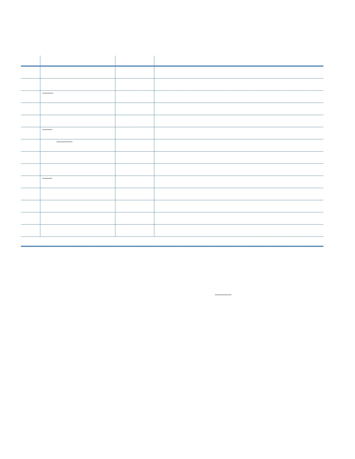
7 PWM1 Either PWM output 1
8 [reserved] - Do not connect
9DTR
/ SLEEP_RQ/ DI8 Either Pin sleep control line or digital input 8
10 GND - Ground
11 AD4 / DIO4 Either Analog input 4 or digital I/O 4
12 CTS
/ DIO7 Either Clear-to-send flow control or digital I/O 7
13 ON / SLEEP
Output Module status indicator
14 VREF Input Voltage reference for A/D inputs
15 Associate / AD5 / DIO5 Either Associated indicator, analog input 5 or digital I/O 5
16 RTS
/ DIO6 Either Request-to-send flow control, or digital I/O 6
17 AD3 / DIO3 Either Analog input 3 or digital I/O 3
18 AD2 / DIO2 Either Analog input 2 or digital I/O 2
19 AD1 / DIO1 Either Analog input 1 or digital I/O 1
20 AD0 / DIO0 Either Analog input 0, digital IO 0
* Function is not supported at the time of this release
Table 2: Pin assignments for the XBee-PRO Modules
(Low-asserted signals are distinguished with a horizontal line above signal name.)
Pin # Name Direction Description