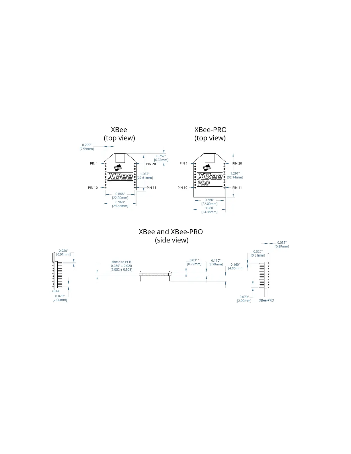
Mechanical drawings of the XBee/XBee-PRO RF Module
XBee / XBee-PRO RF Modules 802.15.4 Product Manual 11
Antenna options
The ranges specified are typical when using the integrated whip (1.5 dBi) and dipole (2.1 dBi)
antennas. The printed circuit board (PCB) antenna option provides advantages in its form factor,
however, it typically yields shorter range than the whip and dipole antenna options when
transmitting outdoors.For more information, refer to the XBee and XBee-PRO OEM RF Module
Antenna Considerations Application Note.
Mechanical drawings of the XBee/XBee-PRO RF Module
Figure 1: Mechanical drawings of the XBee / XBee-PRO OEM RF Modules (antenna options not
shown). The XBee and XBee-PRO RF Modules are pin-for-pin compatible.
Mounting considerations for the XBee / XBee-PRO RF Module
The XBee modules are designed to mount into a receptacle (socket) and therefore do not require any
soldering when mounting them to a board. The XBee-PRO Development Kits contain RS-232 and USB
interface boards which use two 20-pin receptacles to receive modules.

 Loading...


