AT commands I/O settings commands
Digi XBee3® 802.15.4 RF Module User Guide
113
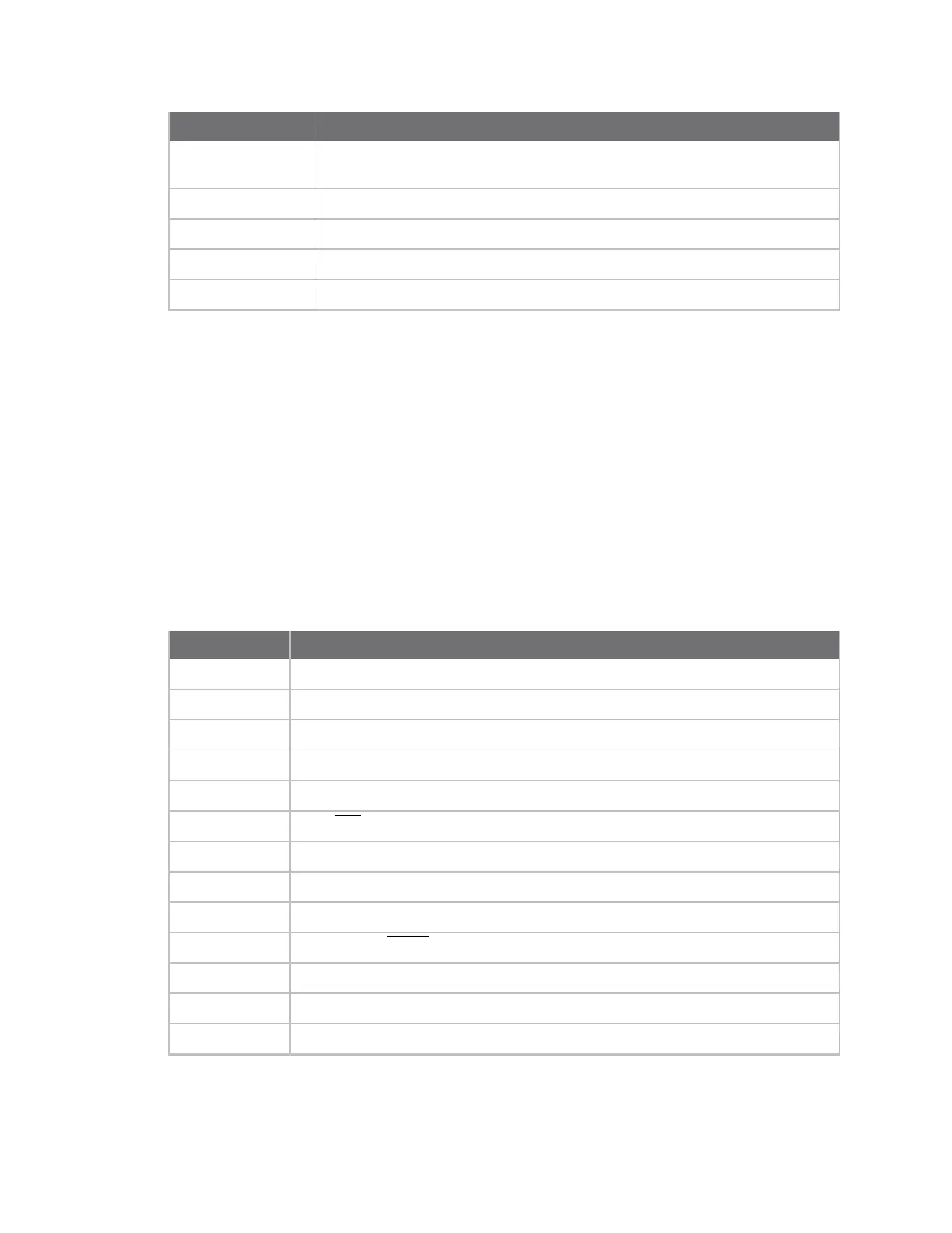
Parameter Description
1
SPI_MISO for the through-hole device
N/A for the surface-mount and micro device
2 N/A
3 Digital input
4 Digital output, low
5 Digital output, high
Default
0
PR command
The bit field that configures the internal pull-up/down resistor status for the I/O lines.
n If you set a PR bit to 1, it enables the pull-up/down resistor
n If you set a PR bit to 0, it specifies no internal pull-up/down resistor.
The PD (Pull Direction) parameter determines the direction of the internal pull-up/down resistor.
PR and PD only affect lines that are configured as digital inputs (3) or disabled (0).
By default, pull-up resistors are enabled on all disabled I/O lines.
The following table defines the bit-field map for PR and PD commands.
Bit I/O line
0
DIO4
1 DIO3
2 DIO2
3 DIO1
4 DIO0
5
DIO6/RTS
6 DIO8/DTR/Sleep_Rq
7 UART_DIN
8 DIO5/Associate
9
DIO9/Awake_SLEEP
10 DIO12
11 DIO10/PWM-RSSI
12 DIO11
 Loading...


