I/O support Mixed network considerations
Digi XBee3® 802.15.4 RF Module User Guide
43
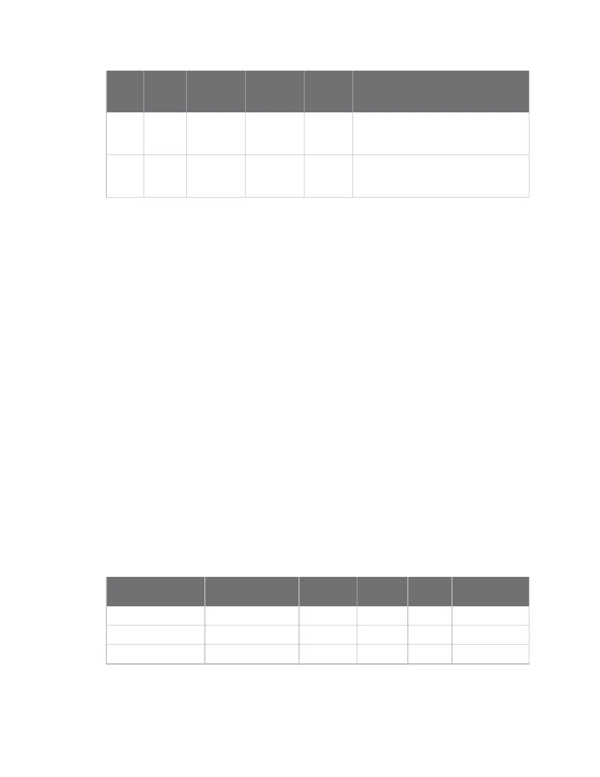
Source
Source
AO
value Destination
Destination
AO value
Data
format API frame on receiver
S1 or
S2C
N/A XBee3 0 or 1 Legacy RX (Receive) Packet: 64-bit address IO
frame - 0x82 / RX Packet: 16-bit address
I/O frame - 0x83
S1 or
S2C
N/A XBee3 2 Legacy RX (Receive) Packet: 64-bit address IO
frame - 0x82 / RX Packet: 16-bit address
I/O frame - 0x83
Refer to I/O sample data format for more information on the format of the incoming I/O sample data.
Mixed network considerations
If you use a mixed network of XBee3 and legacy S1 or S2C devices, you must setAOto 2 in order to
transmit sample data that is compatible with these devices.
Regardless of theAOsetting, if an XBee3 802.15.4 RF Module receives an I/O sample packet from an
S1 or S2C device, it always outputs the legacy data format.
Digital I/O support
AO command determines the I/O lines available for sampling. By default, AO is configured to be
compatible with legacy devices.
n ConfigureAOto 0 or 1 to make digital I/O available on lines DIO0 through DIO14 (D0
command- D9 commandandP0 command- P4 command).
n ConfigureAOto 2 to make digital I/O available on lines DIO0 through DIO8 (D0- D8 command).
This provides compatibility with S1 and S2C devices and is the default configuration.
See Legacy support for more information.
Digital sampling is enabled on these pins if configured as 3, 4, or 5 with the following meanings:
n 3 is digital input.
l Use PR command to enable internal pull up/down resistors for each digital input. Use PD
command to determine the direction of the internal pull up/down resistor.All disabled and
digital input pins are pulled up by default.
n 4 is digital output low.
n 5 is digital output high.
Function
whenAO= 0 or 1
Legacy Function
whenAO= 2 Micro Pin SMT Pin TH Pin AT Command
DIO0 DIO0 31 33 20 D0 command
DIO1 DIO1 30 32 19 D1 command
DIO2 DIO2 29 31 18 D2 command
 Loading...


