AT commands I/O sampling commands
Digi XBee3® 802.15.4 RF Module User Guide
117
Default
N/A
IR command
Set or read the I/O sample rate to enable periodic sampling. When set, this parameter causes the
device to sample all enabled DIO and ADC at a specified interval.
To enable periodic sampling, set IR to a non-zero value, and enable the analog or digital I/O
functionality of at least one device pin (see D0 command-D8 command, P0 command-P2 command.
WARNING! If you set IR to 1 or 2, the device will not keep up and many samples will be lost.
Parameter range
0 - 0xFFFF (x 1 ms)
Default
0
IC command
Set or read the digital I/O pins to monitor for changes in the I/O state.
IC works with the individual pin configuration commands (D0 - D9, P0 - P5). If the device detects a
change on an enabled digital I/O pin, it immediately transmits a digital I/O sample to the address
specified by DH + DL. If sleep is enabled, the edge transition must occur during a wake period to
trigger a change detect.
The data transmission contains only DIO data.
IC is a bitmask you can use to enable or disable edge detection on individual digital I/O lines. Only
DIO0 through DIO15 can be sampled using a Change Detect.
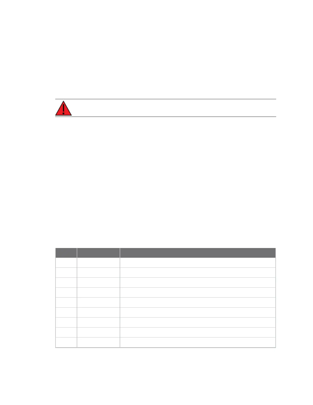
Bit field
Bit I/O line Device pin
0 DIO0 Micro pin 31/SMT pin 33/TH pin 20
1 DIO1 Micro pin 30/SMT pin 32/TH pin 19
2 DIO2 Micro pin 29/SMT pin 31/TH pin 18
3 DIO3 Micro pin 28/SMT pin 30/TH pin 17
4 DIO4 Micro pin 23/SMT pin 24/TH pin 11
5 DIO5 Micro pin 26/SMT pin 28/TH pin 15
6 DIO6 Micro pin 27/SMT pin 29/TH pin 16
7 DIO7 Micro pin 24/SMT pin 25/TH pin 12
8 DIO8 Micro pin 9/SMT pin 10/TH pin 9
 Loading...


