DG-
FS1526 User Manual
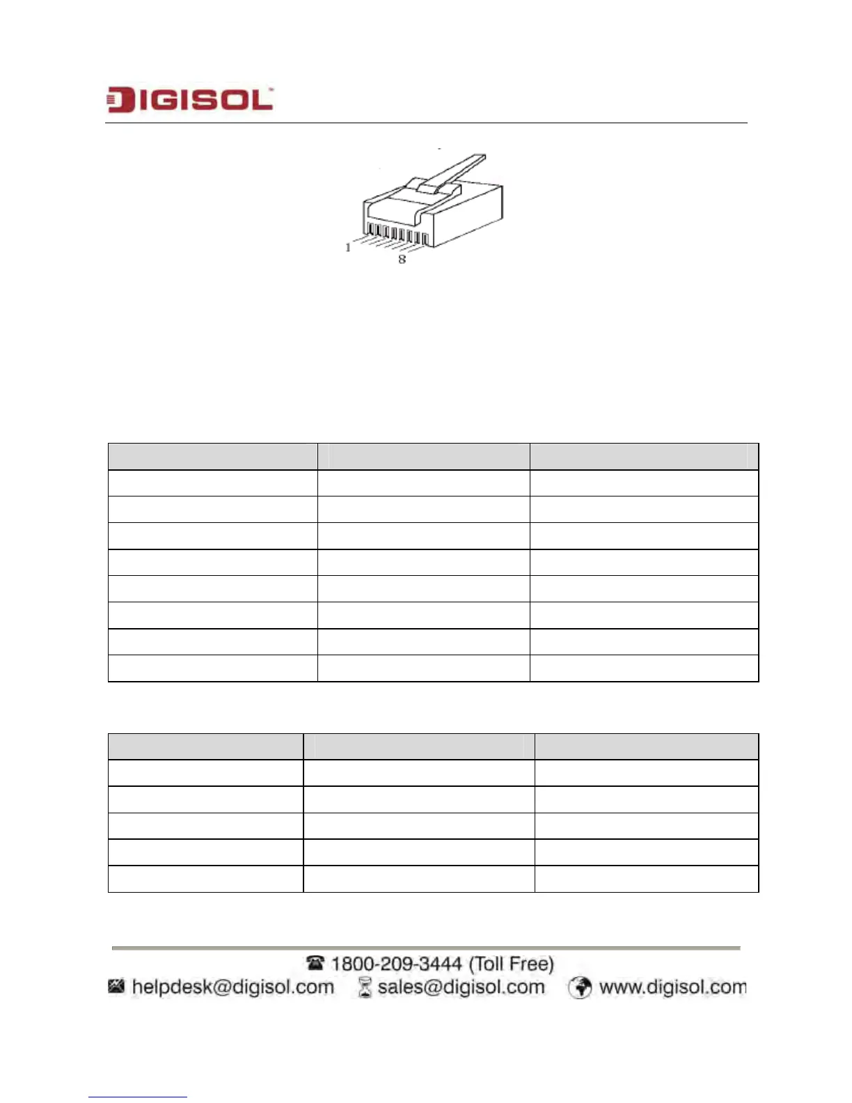
The following figure describes the line sequence of Ethernet cable:
F
igure 1 Pinout of Ethernet interfaces
Crossover cable: Refer to 0 to connect one end of the ne
twork cable. Refer to 0 to connect
the other end.
Straight-through cable: Refer to 0 to connect both ends of the network cable.
T
able 1.
Pinout of RJ-
45 straight-through cable
No. Defini
tion
Color
1 T
XD+ Orange and white
2 TXD- Orange
3 RXD+ Green and white
4 -
Blue
5 -
Blue and white
6 RXD- Green
7 -
Brown and white
8 -
Brown
T
able 2.
Pinout o
f RJ-45 crossover cable
No. Defini
tion
Color
1 RXD+ Green and white
2 RXD- Green
3 T
XD+ Orange and white
4 -
Blue
5 -
Blue and white
13