1. Hook up the wires from the track to the RAIL A & RAIL B terminals
on the DCS50. Insert the wire from one rail of the track into the
RAIL A terminal on the back of the DCS50. Insert the wire from the
other rail of the track into the RAIL B terminal. Turn the screw
counter clockwise to open the connector and clockwise to close it
once the wire is in place.
2. Plug the barrel connector from the PS315 into the POWER IN jack
on the back of the DCS50. Plug the body of the PS315 in to a regu-
lar wall outlet.
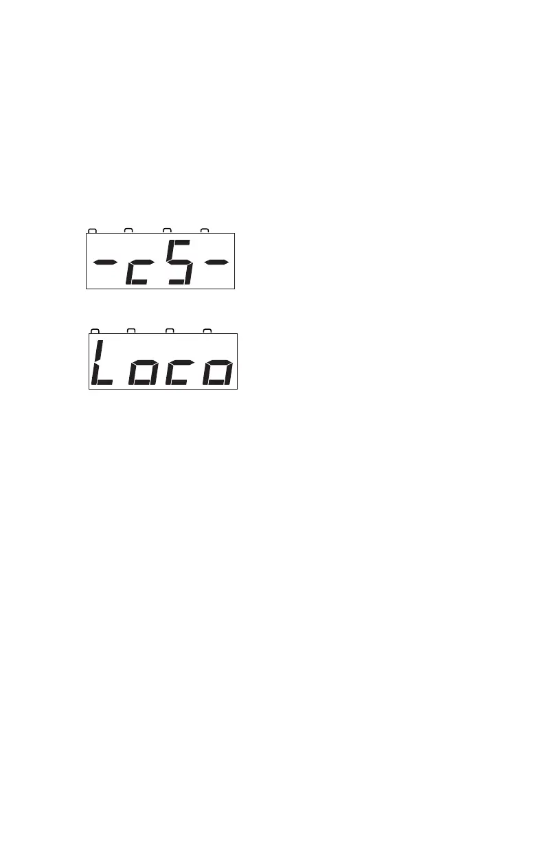
Once power is applied, the DCS50 will
briefly flash “-cS-” to let you know it
is running as a command station.
The DCS50’s display will change auto-
matically to “Loco” or the last address
that was on the throttle when you turned
it off.
3. Turn track power on. Check the TRACK STATUS Indicator. If it is
on, you are ready to go. If the TRACK STATUS Indicator is unlit,
press the POWER key to turn track power on. When track power is
on the TRACK STATUS Indicator will be lit.
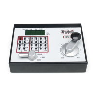
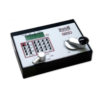
6.0 DCS50 Front Panel Controls And Indicators
Before you select and run a locomotive, take a few minutes to look at the
DCS50’s controls and display.
1. The Throttle Knob is the large silver and black knob on the right side
of the DCS50. The Throttle Knob controls locomotive speed from
STOP to FULL speed. Turn it clockwise to increase speed and
counter clockwise to decrease speed.
2. The Direction Control Lever is the small silver lever (located on the
left side of the DCS50) that controls the locomotive’s direction of
travel, FORWARD or REVERSE. This knob also controls the
BRAKE. When you have a loco address selected and the Direction
Control Lever lever is in the BRAKE position, the BRAKE
INDICATOR will blink until the loco stops and then remain on
steady to let you know that the brake is on. When you move the