Connecting the Waste Lines
Doc. 031879-01 3/03 B-23
B.10 Connecting the Waste Lines
The ICS-1000 has the following waste lines:
• PUMP WASTE carries prime waste from the pump.
• TO WASTE OUT carries sample overflow from the injection valve.
• WASTE, GAS SEPARATOR carries system waste from the suppressor.
Untape the coiled waste lines from the rear panel. Place the ends of the
PUMP
WASTE
and TO WASTE OUT lines into a waste container.
Direct the
WASTE, GAS SEPARATOR line from the top of the ICS-1000 to the rear
panel. Snap the line onto one of the tubing clips on the rear panel. Connect the line
to the gas separator waste tube (see Section B.10.1
).
NOTE To prevent waste from siphoning back into the system,
check the lines periodically to be sure they are not bent,
pinched, or elevated at any point.
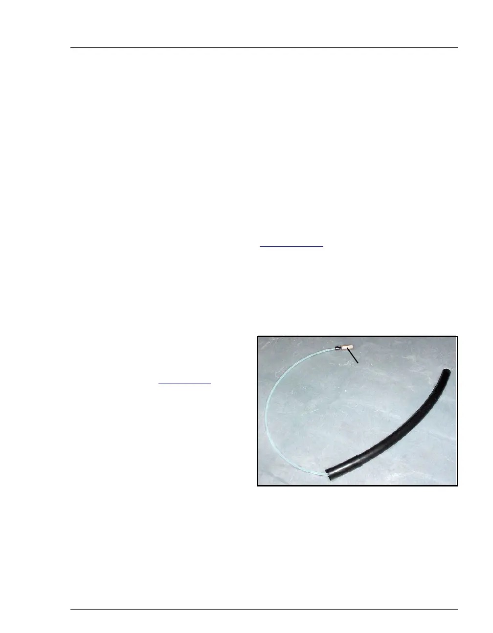
B.10.1 Installing the Gas Separator Waste Tube
1. Locate the gas
separator waste tube
assembly (see
Figure B-21
) in the
ICS-1000 Ship Kit
(P/N 057905).
2. Connect the
WASTE,
GAS SEPARATOR
line to the 3-mm
(1/8-in) ID white
Teflon tubing on the
gas separator waste
tube assembly.
Figure B-21. Gas Separator Waste Tube Assembly
3. Place the gas separator waste tube assembly into the waste container.
Make sure the tubing junction (where the white Teflon tubing meets
the black polyethylene tubing) is above the top of the container and
Connect the
WASTE, GAS
SEPARATOR line
here

 Loading...


