Operation Manual: Evolution Series
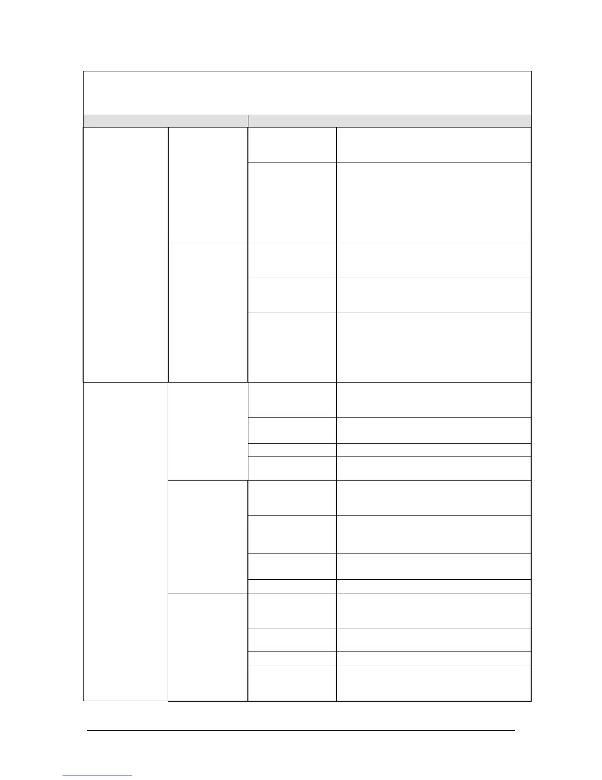
Display/Keypad
PROBLEM POSSIBLE SOLUTION
Fuse
Check if the 0.5 amp fuse located on the
5151 PCB is blown.
Replace is needed.
Shaft not
rotating-unit
heats
properly
Cable
connectors
Check drive motor connection on 5151
PCB at location “J6” (see figure 3) for
loose wire connection or damage pins.
Repair as necessary.
Check motor drive connection on the
drive motor itself for loose wire
connection or damaged pins.
Re-cycle power
Turn instrument off.
Wait approximately 2 minutes and
restart unit.
LCD display
Make sure that the display assembly is
mounted securely on the bezel.
Replace the LCD display.
DRIVE MOTOR
Shaft rotate-
not heating
properly
Stage board
Check that all socket chips are inserted
properly.
Note: Make sure you do not bend the
leads when removing and reinstalling the
chip.
Replace the stage board if necessary.
LED display
cable
Check the LED cable going from the 5150
board to the LED board (5104) for any
loose wires on the crimp connector.
Cabling
Connection
Check wiring from the PC board to the
5154 (stage board).
LED board
Replace the 5104 LED board display.
LED display
not scrolling/
locking up
Interface board
Replace the 5150- interface board that
causes the LED board not to function.
LED display
cable
Check the ribbon cable that goes from
the LED connector to the 5150 board for
any loose wires or crimps.
LED display
(seven
segment)
Check for any loose or shorted
connection on the LED display board.
LED display
board
Replace the LED display board.
No LED
display
Interface board Replace the interface board (5150).
LED display
cable
Check the LED cable going from the 5150
board to the LED board (5104) for any
loose wires on the crimped connector.
LED display
Replace the LED seven-segment display if
necessary.
LED board
Replace the 5104 LED board display.
LED DISPLAY
Some LED
display digits
missing
Interface board Replace the 5150 interface board that
causes the LED board not to function
properly.