38
EN
IP2348EN
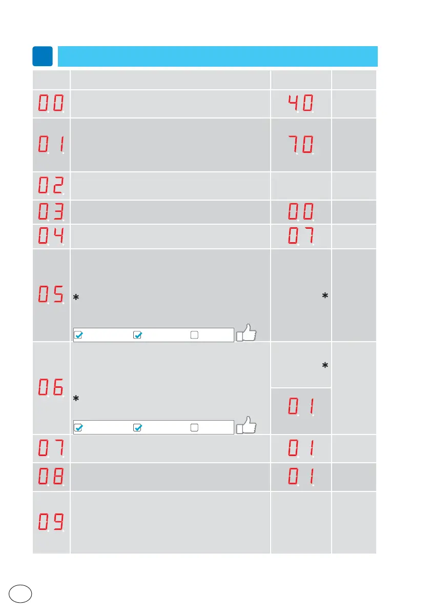
11.2 Main control board parameters
i
In the “INSTALLATION SETTINGS” column you can note the modified setting values.
Parameter Description
Factory
setting
Installation
setting
High Speed Opening (10÷80cm/s)
Sets the maximum opening speed.
(10= 10cm/s; 70= 80cm/s
Low speed
(05÷69= 05÷80cm/s; 70= automatic)
The low speed is self adjusting to optimal operation if this pa-
rameter is set to max. Depending on authority or installation
requirements the low speed, distance opening and/or closing
can be further reduced.
High Speed Closing (10÷80cm/s)
Sets the maximum closing speed.
(10= 10cm/s; 70= 80cm/s)
AUTOMATIC
Hold Open Time (00÷60s)
The general hold open time for inner and outer impulses.
Key Hold Open Time (00÷60s)
Hold open time for key impulse.
Lock Configuration (main control) (10÷12)
10= No lock.
11= Antipanic lock (locked with power – LDP).
12= Standard lock (locked without power – LD) and bi-stable
lock (LDB).
NOTE: the bistable block is not automatically learned and
must be selected 12.
NOTE: if the Configuration Tool CT is used, disable the “learn
access”:
Learn AccessMMI Read accessMMI Write access
AUTOMATIC
Lock release (00÷01)
00= Off
01= On
If“LockRelease”is On the door will apply force in the closing
direction when the lock is un locking.This is made to prevent a
lock from being stuck in locked position when opening.
NOTE: If lock type is set manually (paramenter 5) set 01.
NOTE: If the Configuration Tool CT is used, disable the “learn
access”:
Learn AccessMMI Read accessMMI Write access
AUTOMATIC
(DAS200TRG)
Presence Impulse 1 Configuration (00÷01)
00= N.O.
01= N.C.
Presence Impulse 2 Configuration (00÷01)
00= N.O.
01= N.C.
Presence Impulse Monitoring (00÷02)
00= No monitoring of precense impulse.
01= Set to “01” if one Presence impulse sensor shall be mo-
nitored (if only one sensor is used this sensor has to be
connected to terminal 9, Presence impulse 1).
02= Set to“02” if two Presence impulse sensors shall be
monitored.
TO BE SET