HM= H-39
80
max 70
19
H
27
2030
6
12
KPAM45
9
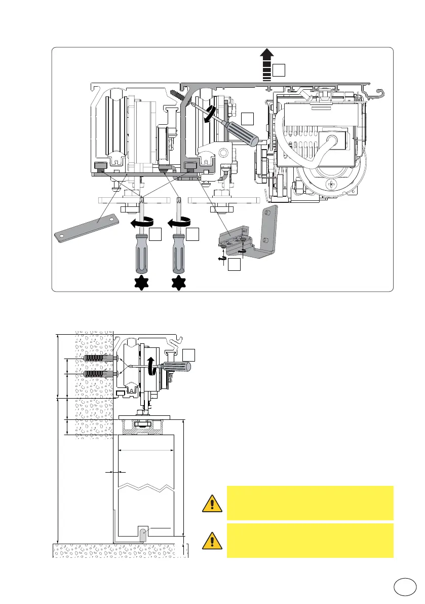
WARNING: the fastening of the box to the
wall must be sufficient to sustain the door
wing weight.
WARNING: do not damage the wheel guide
during assembly. Clean the guide thorou-
ghly beforeinstalling the wings.
9
EN
IP2348EN
5.4 Rear operator installation
5.3 Removing the front casing
Unless otherwise specified, all measurements are
expressed in millimetres (mm).
The figure shows the
measurements for fastening the automation to the wall,
considering that the automation door wings are made
using profiles not manufactured by us.
If the door wings
are made with DITEC profiles in the ALU/PAM series: re-
fer to the measurements given in the relative manuals.
Drill a hole in the box using the reference line on the
back and fasten it with M6 Ø12 steel plugs or 6MA
screws (not supplied). Distribute the fixing points ap-
prox. every 400 mm. Make sure the box is positioned
evenly, with its back surface perpendicular to the floor
and not deformed lengthwise by the shape of the wall.
If the wall is not straight and smooth, iron plates must
be fixed to it and then the box in turn fixed to the plates.