10
IP2358EN
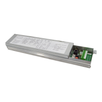
D10 - Stop active
(X3:1-2, X3:3-4, X3:28-29, X13:2-5, X2:4-5)
LED is also active in fail mode.
Observe display and D15 ERROR LED
D13 - Open (S2) active
D12 - Close Limit active
D28 - Power ON to Open contactor
D16 - Close (S3) active
D14 - Open Limit active
D29 - Power ON to Close contactor
D15 - Error LED - Shows error codes
LEDs:
4. CONTROL UNIT SET-UP
The set-up must be performed with the motor off. Follow carefully the steps as described in the procedures, DO
NOT activate any safety, hand controls or radio controls unless specifically requested by the procedure.
Basically the set-up of the control and the right coupling control/motor must be performed by the installer.
4.1 SET-UP MODE ACTIVATION
To enter the control unit programming mode place the DIP1 of the switch (S4) in ON.
During set-up the control unit will work only in dead man mode.
To return to the normal operating mode, place the DIP1 of the switch (S4) in OFF.
4.2 BASIC PROGRAMMING
The control unit is supplied with a basic setting performed at the factory which can be restored at any time with the
reset procedure (see paragraph 4.3).
Before beginning the programming procedure:
1. Open the cover of the unit.
2. Make sure all the connections have been made correctly and that the emergency stop or other safety devices are
not activated. Otherwise the display shows the stop symbol active .
3. Find the buttons OPEN (S2) - CLOSE (S3) - STOP (S1) and the 4 switches (S4) on the board.
4. Ensure that the LED D10 is not flashing (in case it flashes, check again point 2).
8k2 OR
PNEU.
EDGE
SAFETY
PHOTO
X3
SAFETY
HOTO
HOTO 2
4 V
OUTPU
SPEED INPU
1/2 OPEN
IMIT SW
+24V
OPEN
IMIT SW
CLO
IMIT SW
O FUNCTIO
CLOS
OPEN
STO
MER. STO
2
I
OFF <->ON
OPEN
S2
TOP (S1)
LOSE (S3
S4
FIG. 4