00:00.
2 1:00
2 1:00 2 1:00
2 1:0 1
1 2 3 4 5
02
03
04
03
The same happens if you choose a parameter that does not match with the connected terminals.
Through PARAMETER 21 you can select the type of safety edge.
22
IP2358EN
13.2 SAFETY EDGE
Safety edge connection: in case of resistive safety edges 8.2KΩ (type SOFA and SOFB) or pneumatic safety edges, con-
nect the wires to the terminals 23 and 24 of X3.
In case of optoelectronic safety edge, connect the wires to the terminals 25, 26 and 27 of X3 (respecting the color order).
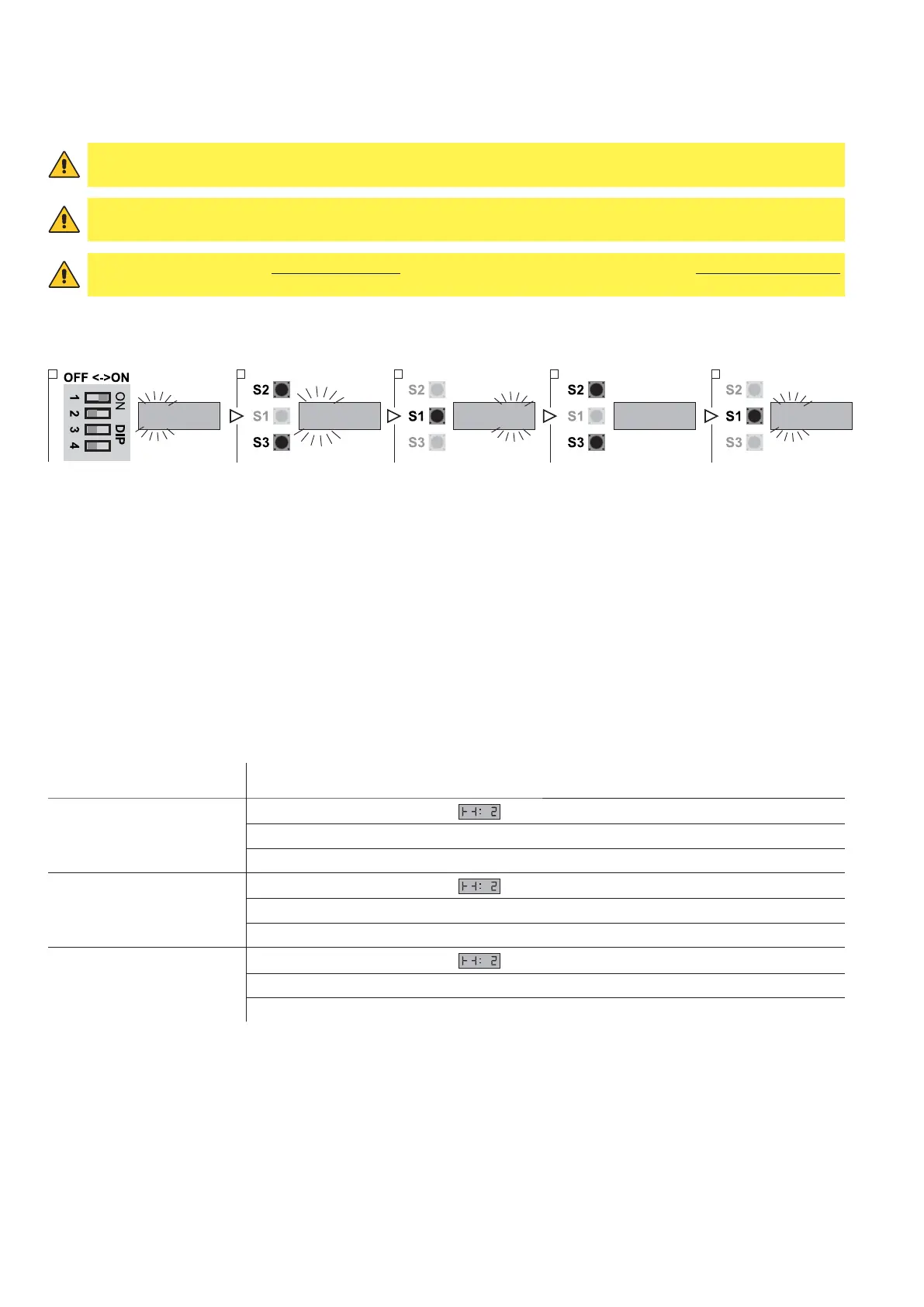
1. Put DIP 1 (S4) in ON position, PARAMETER digits start blinking
2. Using the buttons OPEN (S2) and CLOSE (S3) select the parameter 21
3. Access the field VALUE pressing STOP (S1)
4. Using the buttons OPEN (S2) and CLOSE (S3) vary the value
- VALUE 01: PNE / DW pneumatic.
- VALUE 02: Safety edge with resistive contact 8.2KΩ.
- VALUE 03: Optoelectronic edge.
- VALUE 04: Special LP / DW pneumatic.
5. Press STOP (S1) to confirm.
6. To leave the set-up mode, place the DIP1 in OFF.
SAFETY EDGE FUNCTION DESCRIPTION
In case the safety edge is activated the control unit makes a sequence of commands depending on the door status at
the time of activation:
STATUS OF THE DOOR CONTROL UNIT FEEDBACK
The door is stopped
The display shows the symbol
Closing is prevented
Opening allowed to the UP limit position
The door is opening
The display shows the symbol
Opening continues until the UP limit position is reached
Closing is prevented
The door is closing
The display shows the symbol
In case of impulsive operation mode: it reverses the direction to the complete opening
In the case of dead-man operation mode: it stops and reverses upwards
WARNING: if you choose the optical safety edge (VALUE 03) the terminals 23 and 24 DO NOT have to be connected
by a jumper.
WARNING: if you DO NOT want to use a safety edge, select the VALUE 01 and connect the terminals 23 and 24
with a jumper. The terminals 25, 26 and 27 of X3 must not be connected.
WARNING: the safety edge must be connected before the selection of PARAMETER 21, but do not activated them.
If this happens, the control unit shows an error signal on the display the code