12
IP2358EN
1
2
3
4
5
6
1
2
3
4
5
6
7
8
9
10
11
12
13
14
15
16
17
18
19
20
21
22
23
24
25
26
27
28
29
30
31
1
2
3
4
5
6
X3
PUL
E IN
REF.
WIT
H
ENCODER
THERMO
SPEC
DOOR STOP
AFETY ED
PTI
AL
8k2 O
PNEU.
ED
AFETY
PHOT
GREEN
BROWN
PHOTO
24
UTPUT
SPEED INPUT
2 OPE
LIMIT SW
+24
PE
LIMIT SW
L
E
LIMIT
W
F
N
TI
L
E
OPE
STO
EMER. STO
X13
DATA -
DATA +
GND
+12V
SAFETY CHAIN
123
4
5
6
FIG. 5a
FIG. 5
NRGCAB
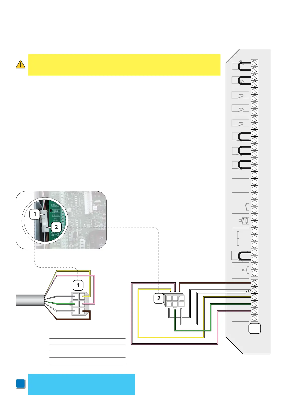
5 OPERATION WITH ENCODER MOTOR
5.1 CONNECTING ENCODER LIMIT SWITCHES
The control unit is pre-set to the type of encoder limit switch.
The encoder limits switch wires are connected according to the diagram of fig. 5.
ATTENTION: if you connect a control unit pre-set for encoder limit switches to a motor with
mechanical limits, the motor does not perform correctly. In particular, the motor will
not find the limit positions and this could put at risk the safety of people and/or things.
The limit switches connector (1) of the multicore cable (NRGCAB) must be connected to the
male connector (2) of the cable the control unit is provided with (Fig. 5a).
1 GREY > GRD
2 GREEN > DATA -
3 WHITE > GRD
4 YELLOW > DATA +
5 PINK > SAFETY
6 BROWN > +12V
i
NOTE:
in case you are not using a Ditec NRGCAB
cable, you have to use a cable with AMP 0172168
connector at both ends