13
IP2358EN
00:00.
1 1:00
1 1:00 1 1:05
1 1:00
1 2 3 4 5
05
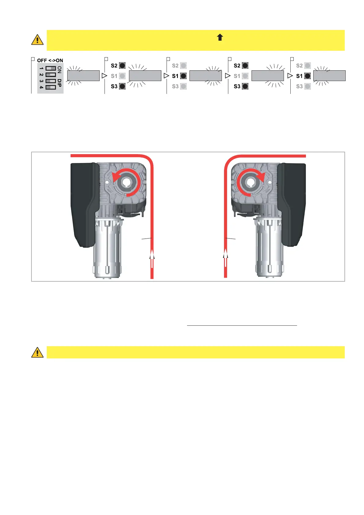
5.2 CONFIGURATION OF ENCODER LIMIT SWITCH
1. Put DIP 1 (S4) in ON position, PARAMETER digits start blinking
2. Select by OPEN (S2) / CLOSE (S3) buttons the number 11
3. Confirm by STOP (S1) button the PARAMETER selected. The VALUE digits start blinking
4. Select by OPEN (S2) / CLOSE (S3) buttons the VALUE:
- VALUE 05: standard installation. Check the rotation direction of the shaft while the door going up (opening) as
shown in fig. 5b
;
- VALUE 06: not standard installation. While the door going up (opening), the rotation direction is opposite com-
pared to the previous case.
5. To confirm the VALUE selected and return to PARAMETER digits press STOP (S1) button
6. To leave the set-up mode, place the DIP1 in OFF..
After selecting the type of digital limit switch with encoder it is necessary to cut off the power supply (by disconnecting
the plug or by turning OFF the main switch) and then to connect it once again in order to allow the communication
between the encoder and the control unit.
WARNING: Please follow the installation requirements of the Ditec motors.
For example, if a motor with encoder is installed in a way which the encoder direction is reversed, it will not run cor-
rectly and may put at risk things and/or people.
Ditec disclaims any responsibility from the consequences of an installation not accomplished according to this policy.
After the selection of the encoder limit switch, it is necessary to proceed with the limit switches adjustment.
door door
FIG. 5b
WARNING: Connecting the motor and pressing the up button ( ) the door must go up, otherwise reverse the
phases (see par. 2.2)