16
IP2358EN
6.
OPERATION WITH MOTOR WITH MECHANICAL LIMIT SWITCHES
6.1 CONNECTING MECHANICAL LIMIT SWITCHES
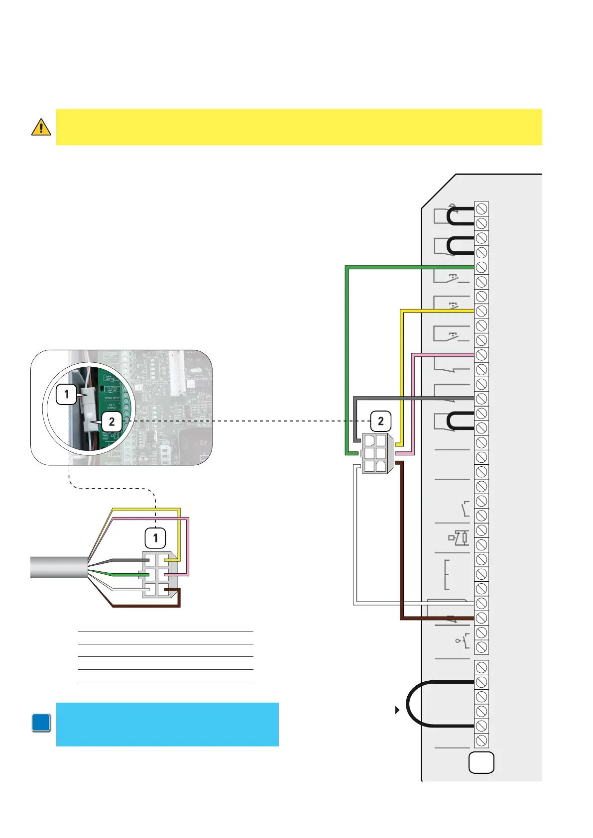
The wiring is preset for encoder limit switch. To set-up the control unit to mechanical limit switch it’s needed to
modify the wiring as shown below (fig. 6).
The limit switches connector (1) of the multicore cable NRGCAB must
be connected to the male connector (2) of the cable the control unit is
provided with (Fig. 6a).
FIG. 6a
1
2
3
4
5
6
7
8
9
10
11
12
13
14
15
16
17
18
19
20
21
22
23
24
25
26
27
28
29
30
31
1
2
3
4
5
6
X3
UL
E IN
ATA -
ATA +
N
12V
REF
WIT
H
ENCODER
SAFETY EDGE
PTICAL
8k2 OR
PNEU
ED
AFET
HOT
REEN
ROWN
AFETY
HAIN
HOTO 2
24 V
UTPUT
PEED INPUT
2 OPE
IMIT SW.
24V
FUN
TI
TO
MER. STO
X13
OPEN
LIMIT SW.
CLOSE
LIMIT SW.
CLOSE
OPEN
THERMO/SPEC
DOOR STOP
1
2
3
4
5
6
1
2
3
4
5
6
NRGCAB
ATTENTION!
Terminals 2 and 5 of
the connector X13
must be bridged
1
GREY > OPEN LIMIT SWITCH
2
GREEN > OPEN BUTTON
3
WHITE > SAFETY
4
YELLOW > CLOSE BUTTON
5
PINK > CLOSE LIMIT SWITCH
6
BROWN > SAFETY
FIG. 6
WARNING: connect a control unit pre-set for mechanical limits to a motor with encoder limits, the motor does
not perform correctly. In particular, the motor will not find the limit positions and this could put at risk the
safety of people and/or things.
i
NOTE:
In case you are not using a Ditec NRGCAB
cable, you have to use a cable with AMP 0172168
connector at both ends