4
6
RUN
12
1
15
00:00
13:00
1 2
65 7
3 4
13:00
4
6
7
RUN
14
16
1
17
00:00
15:00
1 2
765
3 4
15:00
15
IP2358EN
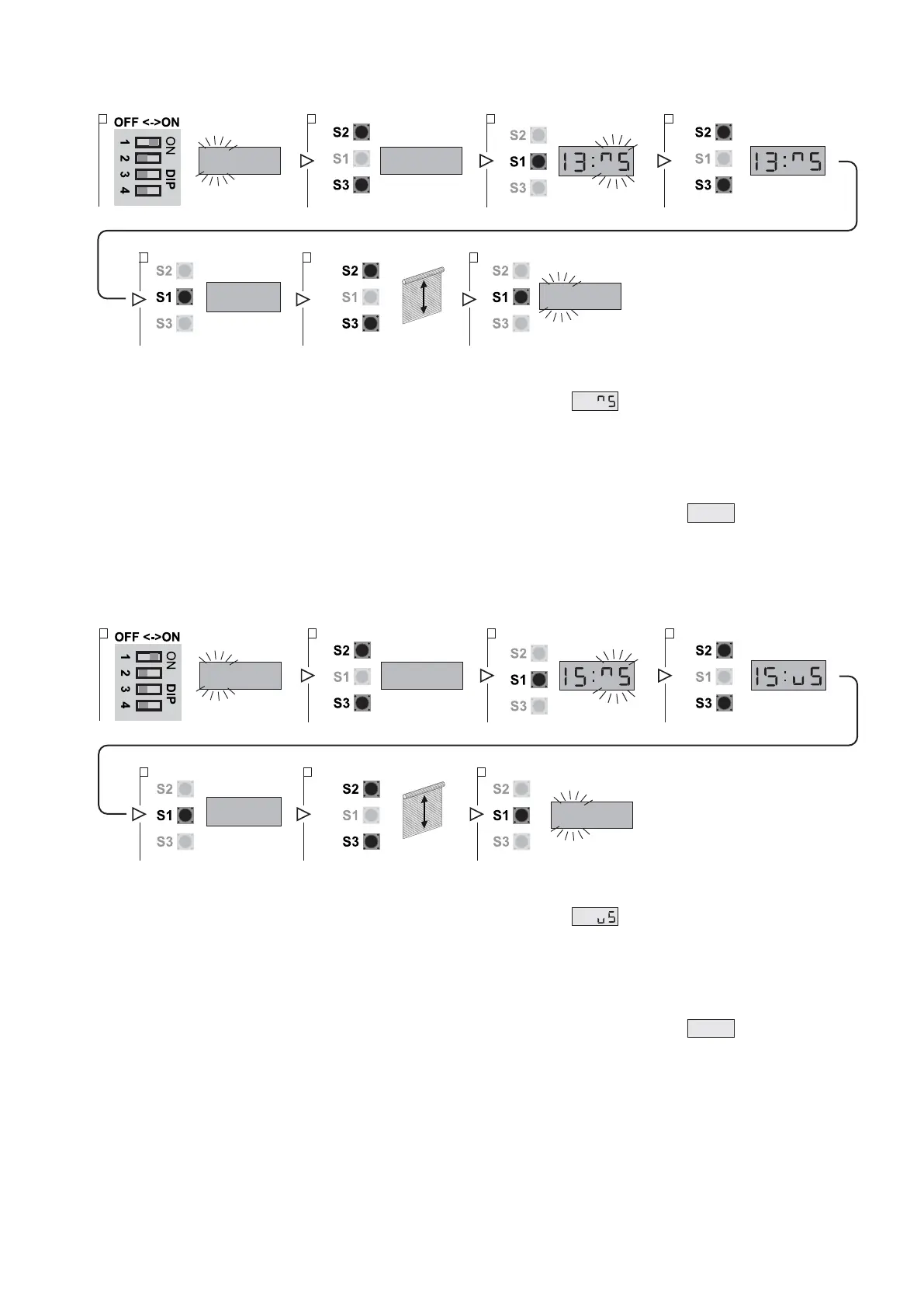
5.4 FINE-TUNING OF ENCODER LIMIT SWITCH
UP LIMIT SWITCH POSITION TUNING
1. Put DIP 1 (S4) in ON position, PARAMETER digits start blinking
2. Select parameter 13 using the buttons OPEN (S2) and CLOSE (S3)
3. Access the field VALUE pressing STOP (S1). In the field VALUE symbol flashes.
4. Using the buttons OPEN (S2) and CLOSE (S3) vary the value:
- from 4 to 1: progressively decrease the UP position;
- from 6 to 9: progressively increase the UP position.
The adjustment range is max ± 0.8% of the travel of the door.
If the value in not to be changed you can return to the field PARAMETER pressing the STOP button (S1).
5. After modifying the VALUE press the STOP button (S1) to confirm: the display will show
RUN
.
6. You can test the varied position of the door by moving it through the buttons OPEN (S2) and CLOSE (S3).
7. Press the STOP button (S1) once again to confirm the tuning and return to the PARAMETER field.
8. To leave the set-up mode, place the DIP1 in OFF.
DOWN LIMIT SWITCH POSITION TUNING
1. Put DIP 1 (S4) in ON position, PARAMETER digits start blinking
2. Select parameter 15 using the buttons OPEN (S2) and CLOSE (S3)
3. Access the field VALUE pressing STOP (S1). In the field VALUE symbol flashes.
4. Using the buttons OPEN (S2) and CLOSE (S3) vary the value:
- from 4 to 1: progressively decreases the DOWN position;
- from 6 to 9: progressively increases the DOWN position.
The adjustment range is max ± 0.8% of the travel of the door.
If the value in not to be changed you can return to the field PARAMETER pressing the STOP button (S1)
5. After modifying the VALUE press the STOP button (S1) to confirm: the display will show
RUN
.
6. You can test the varied position of the door by moving it through the buttons OPEN (S2) and CLOSE (S3).
7. Press the STOP button (S1) once again to confirm the tuning and return to the PARAMETER field.
8. To leave the set-up mode, place the DIP1 in OFF.