00:00.
3 1:00
3 1:00 3 1:00
3 1:00
1 2 3 4 5
01
02
03
02
21
IP2358EN
STATUS OF THE DOOR CONTROL UNIT FEEDBACK
The door is stopped
The display shows the symbol
Closing is prevented
Opening allowed to the UP limit position
The door is opening
The display shows the symbol
Opening continues until the UP limit position is reached
Closing is prevented
The door is closing
The display shows the symbol
In case of impulsive operation mode: it reverses the direction to the complete opening
In the case of dead-man operation mode: it stops and reverses upwards
13. SAFETY DEVICES
13.1 PHOTOCELLS
i
NOTE: Refer to the photocells instructions for the DC supply.
A 24V DC supply for the photocells is available:
- Terminal 18 of X3 (or terminal 4 of X12) for the positive.
- Terminal 19 of X3 (or terminal 2 of X12) for the mass.
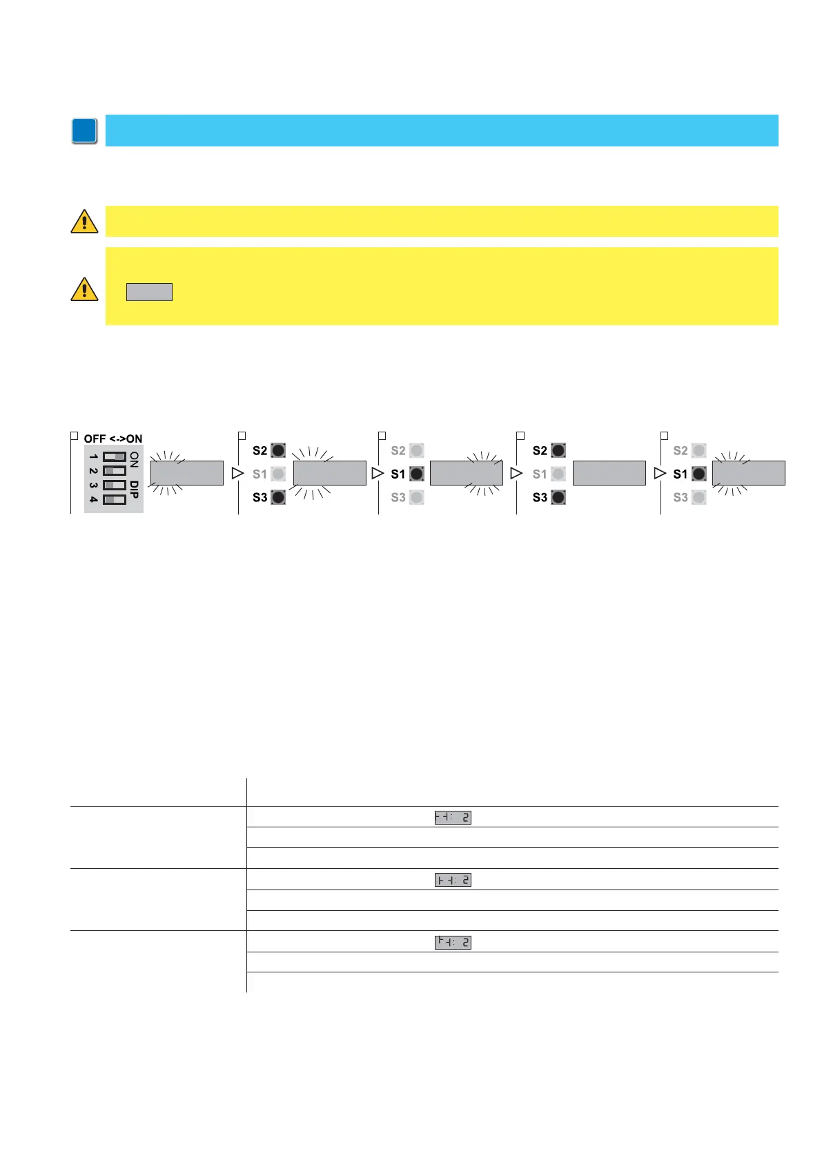
1. Put DIP 1 (S4) in ON position, PARAMETER digits start blinking
2. Using the buttons OPEN (S2) and CLOSE (S3) select the parameter 31
3. Access the field VALUE pressing STOP (S1)
4. Using the buttons OPEN (S2) and CLOSE (S3) vary the value:
- VALUE 00: No photocells connected
- VALUE 01: Connection PHOTO 1 on X12
- VALUE 02: Connection PHOTO 2 on X3
- VALUE 03: Connection PHOTO 1 and 2
5. Press STOP (S1) to confirm.
6. To leave the set-up mode, place the DIP1 in OFF.
PHOTOCELLS FUNCTION DESCRIPTION
In case something interposes between the transmitter and the receiver, this one activates a sequence of commands
depending on the door status when it was interrupted:
WARNING: connect the photocells out contacts between 18 and 22 terminal of the X3 clamp or between 1 and 3
terminal of the X12 clamp, otherwise the photocells test cycle will fails showing on the display the error code
E:05
and preventing the control unit working.
In case of an incorrect connection, restore the correct connections and press stop to start a new test cycle.
ATTENTION! Both the transmitter and the receiver of the photocells must be connected to the same terminals.
Through parameter 31 you can conform the control unit to the type of connection that you are going to select, in order
to activate the corresponding test functions.
This test allows the control unit to constantly check of short circuits or malfunctions that could compromise the safety of
the device. The test thus allows to ensure the safety even in case of single failure as required by the standards EN13241-1
and EN-12453.