17
IP2358EN
01:
01
01:03
01:02
01:04
Hold-to-run OPEN
Hold-to-run CLOSE (Put a bridge in X3 between terminal 23-24 when there is no safety device)
Impulsive OPEN
Hold-to-run CLOSE (Put a bridge in X3 between terminal 23-24 when there is no safety device)
Not in use
Impulsive OPEN; Impulsive CLOSE. REQUIRED WITH RADIO MODULE NRGZENX1 - OPTIONAL
6.2 CONFIGURATION FOR MECHANICAL LIMIT SWITCH
1. Check the configuration; the parameter must be setted for the use of mechanical limit switches:
1 1:00
.
2. Only take care to check the direction of rotation of the motor:
• by pressing the OPEN button (S2), the door must open;
• by pressing the CLOSE button (S3), the door must close.
Otherwise proceed as described in paragraph 2.2.
3. Check that the motor and the control unit are connected as shown in section 6.1 and that the DIP switch S4 is in
OFF.
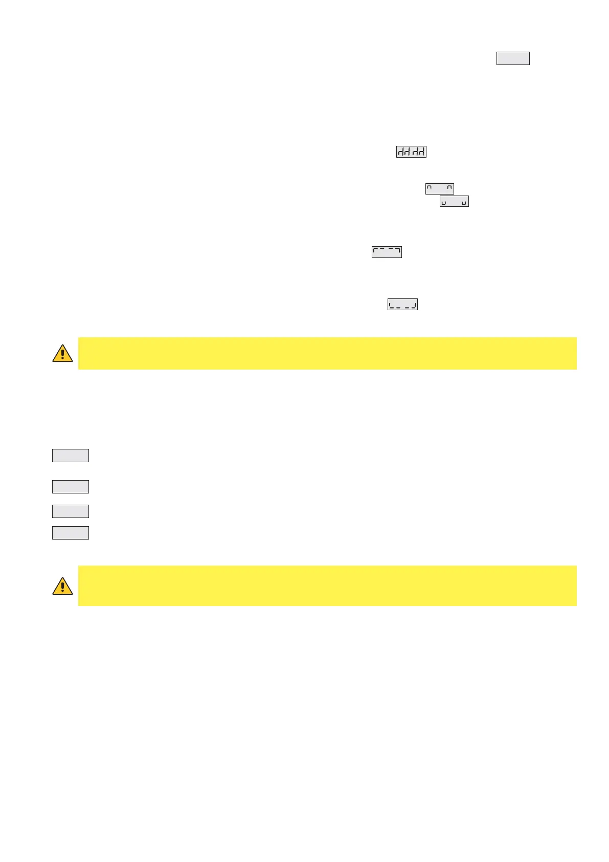
If correctly installed all LEDs are off and the display will show the symbol
which indicates that the motor is
positioned between the two limit switches.
4. Check that:
• pressing the UP button the motor moves the door upwards (the display shows: );
• pressing DOWN button the motor moves the door downwards (the display shows: ).
UP LIMIT SWITCH ADJUSTMENT
Adjust the UP limit switch cam.
When the UP microswitch is pressed, the display will show the symbol:
and the LED D14 will switch on.
DOWN LIMIT SWITCH ADJUSTMENT
Adjust the DOWN limit switch cam.
When the DOWN microswitch is pressed, the display will show the symbol: and the LED D12 will switch on.
The door will move between the two positions set by the limit switches cams according to the operation mode shown
in parameter 01 (see section 7).
WARNING: the standard mode of the control unit is dead-man (parameter 01). During the mechanical limit
switch adjustment use this mode.
Refer to section 7 for the other modes of operation.
7. OPERATION MODE
The control unit is pre-set in dead-man control mode (PARAMETER 01, VALUE 01).
It is possible, however, to define different working modes by modifying the value of PARAMETER 01:
WARNING: it is highly recommended to activate the impulsive mode only after having completed the set-up and
adjustments of the control unit. In particular, during the mechanical limit switches adjustment select always
the dead-man operation mode.
During the encoder limit switches set-up the control unit will only allow the dead-man working mode.