- 27 -
0DT721 01/05/2005 DITEC S.p.A.
ENGLISH
20
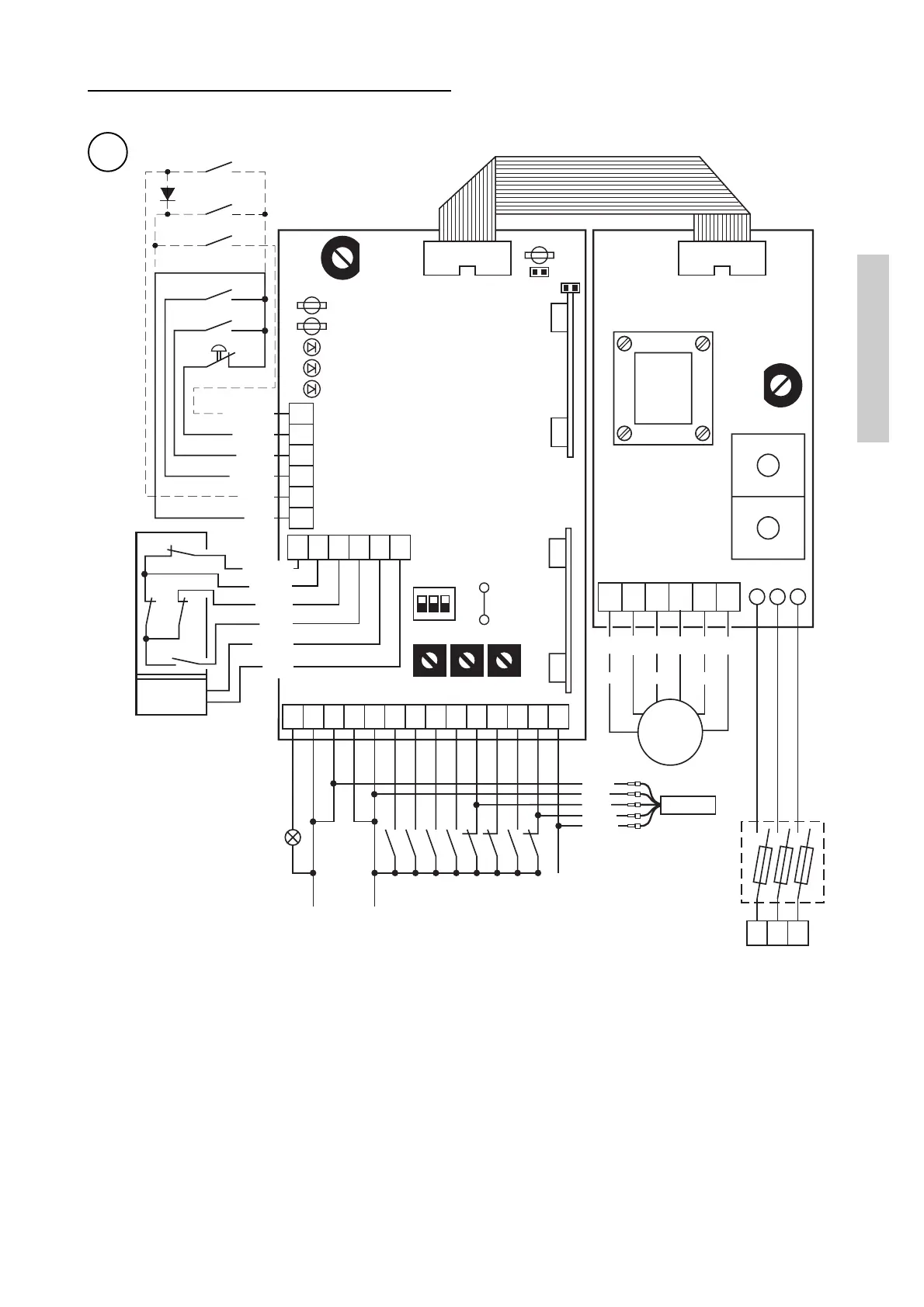
4.3 Operation of the el.control panel
Wire diagram of the QE 44 electrc control panel
DIP SWITCH
DIP 1: Preflashing in opening
OFF = Absent
ON = Fixed to 3 s
DIP 2: Speed selection in openig
OFF = Low speed opening (U V W)
ON = High speed opening (X Y Z)
For FLASH door set in ON
DIP 3: Selection of safety mode
OFF = Exclusion during opening
ON = Enabling during opening
R16 :Closed = Standard brake
Opened = Active brake (T1A)
ADJUSTMENTS
RP = Partial opening adjustment
(1 - 3 s) High speed
(2 - 6 s) Low speed
LC = Flashing advance time in closing (0 - 15 s)
TC = Time for automatic closing (0 - 30 s)
13 12 11 0 -F +F
BRAKE
FA FC
14 0 0 1 1 2
3A3B
4 8 9 20 40 41
RP LC TC
DIP
ON123
R16
OPEN
1 2 3
4P
9P20
F5
Q.E.
F4
W Z V Y U X
L3 L2 L1
F8 A
400 V~
CH
AP
Partial
Opening
MAN.
AUT.
1N5404
T S R
F4 = F630 mA
F5 = F5A
J10
J8
SAFETY
J9
A936A
N
C
T
8/40
FA
FC
LD1
LD2
LD3
EMERGENCY
FS
FR
Brown
Black
Blue
White
Grey
Fuses
Flashing lamp 24V/50W
Output -
24V . . ./0.3 A +
Automatic closing
Open side A
Open side B
Closure
Stop safety
Inversion safety during
the closing
Parziale opening
Safety edge
Phototest
Orange
Black
Blue
White
Red
Brown
Orange
White
Violet
Brown
Blue
Red
M
3~
Motor
1
23
4
5
6
Red
Red
Red