- 11 -
0DT721 01/05/2005 DITEC S.p.A.
ITALIANO
20
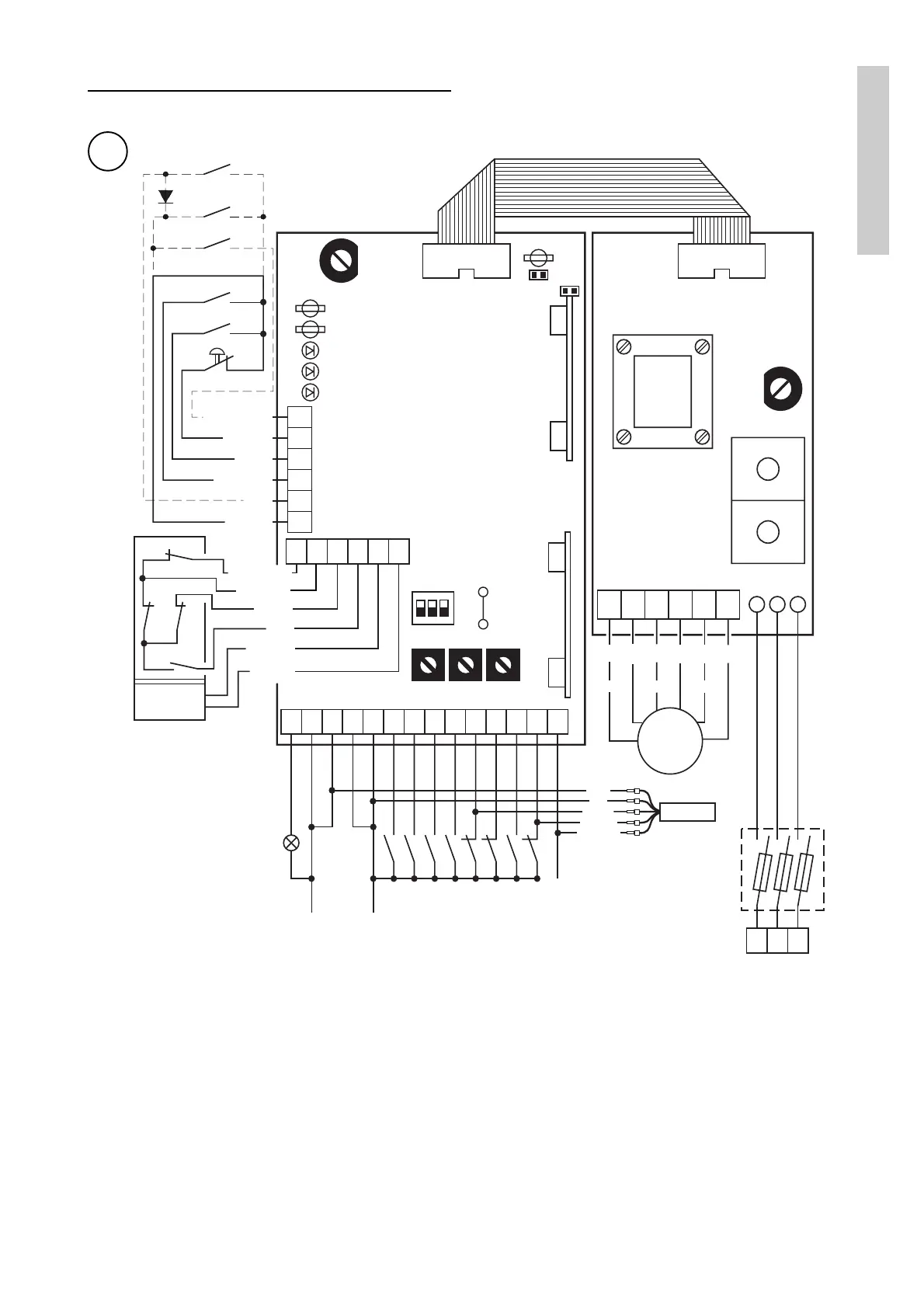
Schema collegamenti apparecchiatura di controllo QE 44
4.3 Funzionamento del quadro elettrico
ON= Abilitazione in apertura
R16 :Chiuso = Freno standard
Aperto = Freno attivo (T1A)
REGOLAZIONI
RP= Regolazione apertura parziale
(1 - 3 s) Alta velocità
(2 - 6 s) Bassa velocità
LC= Tempo anticipo lampeggiante in chiusura (0 - 15 s)
TC= Tempo chiusura automatica (0 - 30 s)
DIP SWITCH
DIP 1: Prelampeggio in apertura
OFF= Assente
ON= Fisso a 3 s
DIP 2: Selezione velocità in apertura
OFF= Apertura a bassa velocità (U V W)
ON= Apertura ad alta velocità (X Y Z)
per porta FLASH posizionare su ON
DIP 3: Selezione modalità sicurezza
OFF= Esclusione in apertura
Arancione
Nero
Blu
Bianco
Rosso
13 12 11 0 -F +F
FRENO
FA FC
14 0 0 1 1 2
3A3B
4 8 9 20 40 41
Lampeggiante 24V/50W
Output -
24V . . ./0.3 A +
Chiusura Automatica
Apertura lato A
Apertura lato B
Chiusura
Sicurezza Stop
Sicurezza d'inversione
in chiusura
Apertura parziale
Sicurezza costa
Fototest
RP LC TC
DIP
ON123
R16
OPEN
1 2 3
4P
9P20
F5
Q.E.
F4
W Z V Y U X
M
3~
Motore
L3 L2 L1
Fusibili
F8 A
400 V~
Arancione
Bianco
Viola
Marrone
Blu
Rosso
CH
AP
AP.PARZ.
MAN.
AUT.
1N5404
T S R
F4 = F630 mA
F5 = F5A
J10
J8
SAFETY
J9
A936A
Marrone
Nero
Blu
Bianco
Grigio
N
C
T
8/40
FA
FC
LD1
LD2
LD3
EMERGENZA
FS
FR
Marrone
1
23
4
5
6
Rosso
Rosso
Rosso