- 21 -
0DT721 01/05/2005 DITEC S.p.A.
ENGLISH
3.2 Accessories and equipment
Standard accessories include 4 fitting iron bars.
The size of the screw anchors to install the bases of
the uprights (not supplied) is M8.
The size of bolts or tie rods to be used to fit the
uprights to the wall (not supplied) is M8.
3.3 Fitting of the door uprights
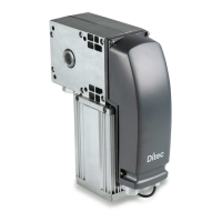
Loosen the three hexagonal head screws and the
relative self-tapping screws and open the covers of the
uprights.
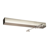
Measure the overall dimensions of the crosspiece
(L).
Mark the exact position of the uprights on the floor.
(Fig. 2)
Fix the bases of the two uprights in correspondence
with the marks, with the special screw anchors. (Fig. 3)
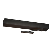
Plumb the uprights and fix them at the indicated
points (A) and (B) with the special iron bars. (Fig. 4)
Make sure that the installation is perfectly
perpendicular by measuring the bias.
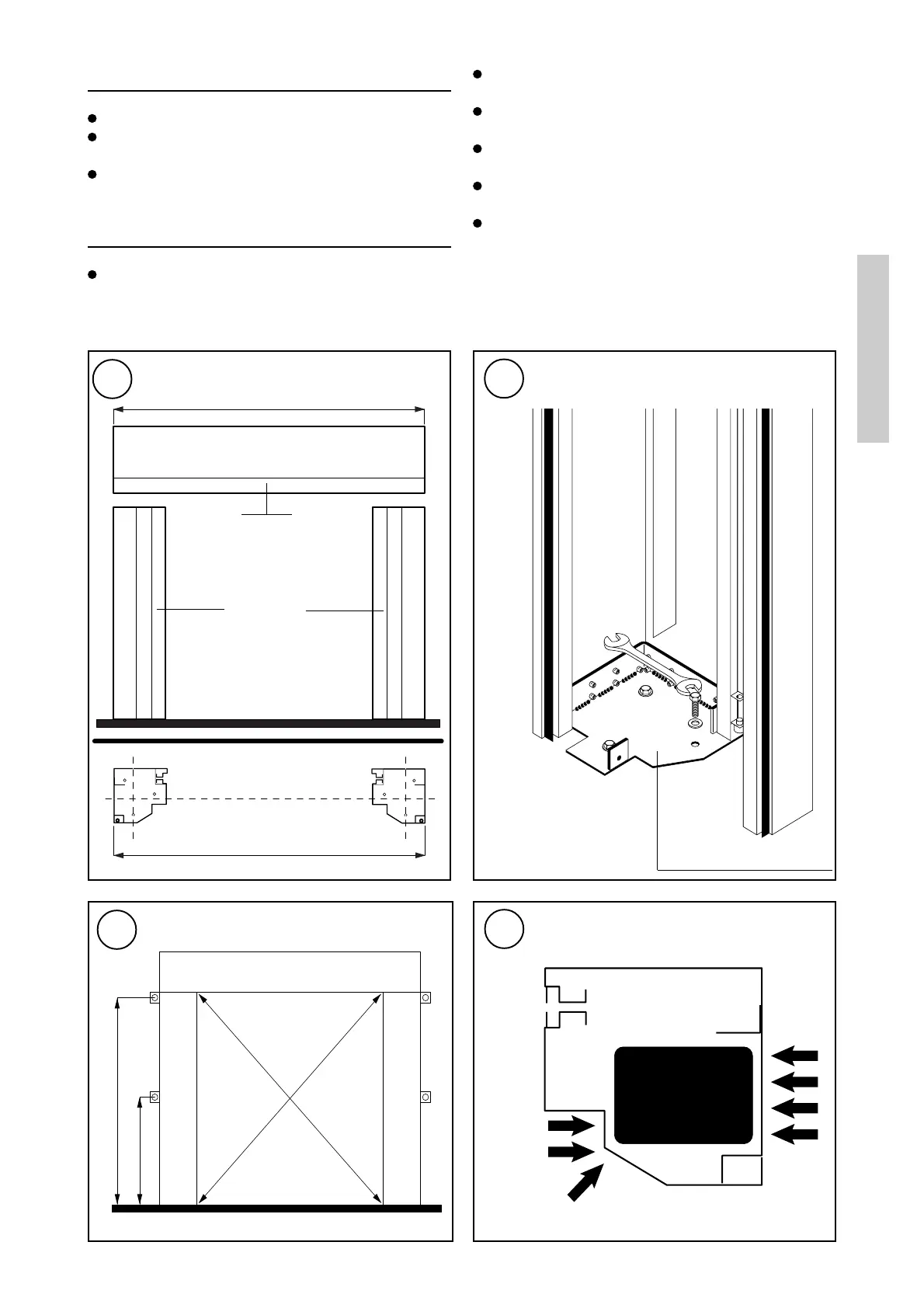
WARNING: it is strictly forbidden to make holes in
the uprights within the sliding area of the
counterweights. (Fig. 5)
5
Counterweight
Upright
section
Do not make holes in this area
3
Base of upright
4
H
1/2 H
"X"
"Y"
X= Y ± 10 mm
A
B
A and B = Anchoring points
2
L
L
Crosspiece
Uprights