- 25 -
0DT721 01/05/2005 DITEC S.p.A.
ENGLISH
4. WIRE CONNECTIONS AND OPERATION
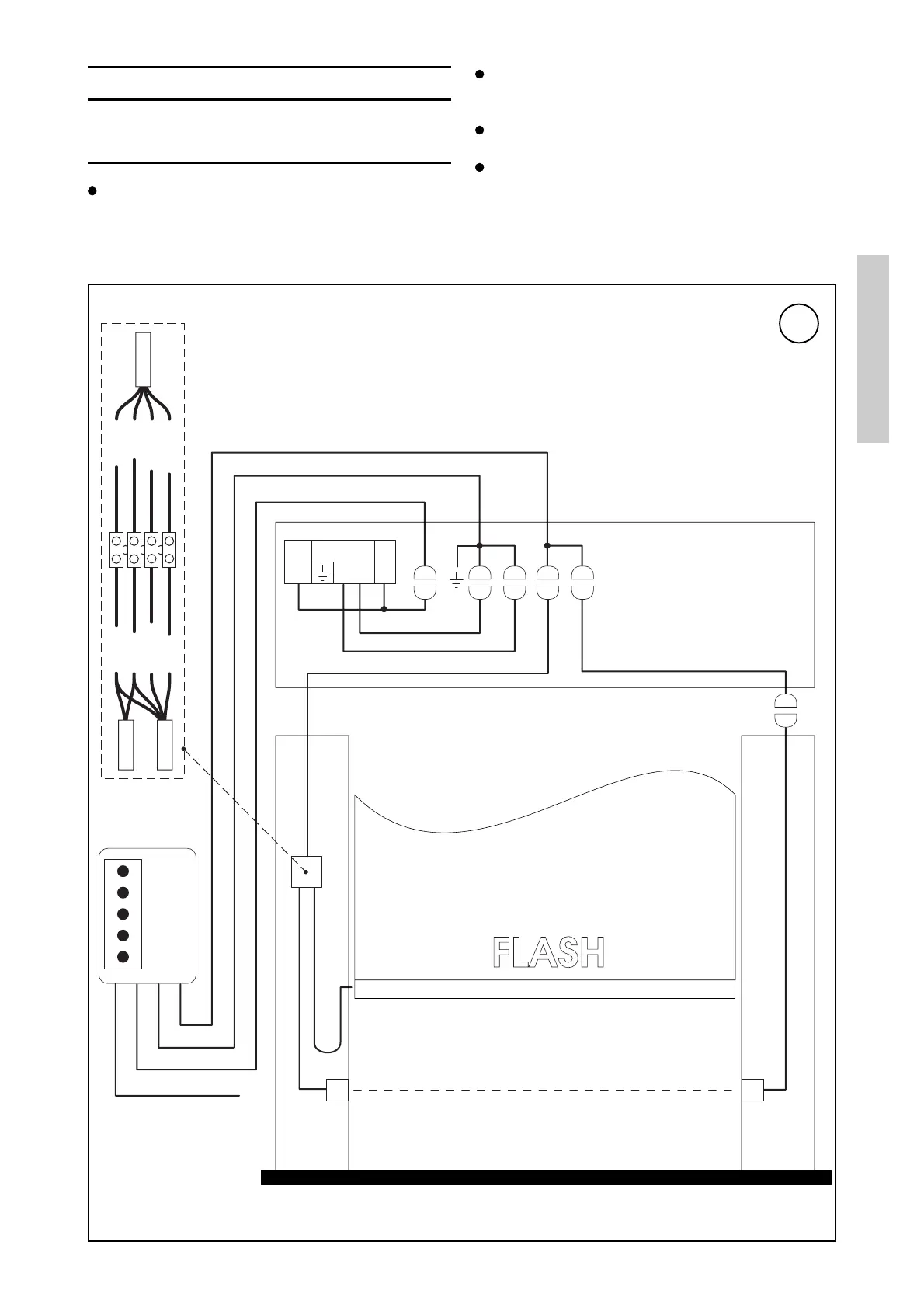
4.1 Connections of the electric control unit to the
automatic system
Figure 17 shows the wire diagrams of cablings and
their positioning in the door; each cabling is identified
by a code indicated on a sticker.
The cablings A935B, A934E, A935A, A935D/E
A934C/D are already routed and fitted in the door
frame (uprights and crosspiece).
The cablings A936A, A933A and A932A are supplied
separately.
Carry out the connections of these wirings by means
of the special quick-release connectors. The cablings
for the last section of connection to the electric control
panel should be routed in the holes on the upper part
of the crosspiece through special protective grommets.
17
FC M F
TX RX
Q.E. 44
400 V 3~
Black
Blue
White
Red
Black
Blue
White
Brown
A934E
A935A
A935B
A936A
A932A
A933A
A935D/E
A934C/D
A935A
A934E
A935B
Mains connection
400 V 3~
Safety photocell
Safety bar