revision: 0
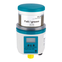
FlexxPump 125 (24V)
User Manual
55
EN-
SCHMIERSYSTEME
DIRECT LUBRICATION SYSTEMS
D L S
Description:
The FlexxPump 125 is properly connected to an external controller via the electrical
interface and connected to the power supply.
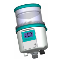
The Pulse-Control-Mode is activated on the FlexxPump 125 and PUL is displayed on
the LCD.
There are no errors on the FlexxPump 125; the FlexxPump 125 is ready for operati-
on; the green LED in the LCD flashes once every 5 seconds.
The FlexxPump 125 sends a permanent output signal (high level) to PIN 4, which
indicates to the external control (PLC) that it is ready for operation. This output signal
must be permanently and continuously present for >3 seconds. Control by the external
controller is only possible if this condition is present.
The control signal 2 seconds with a signal length of 12 (11.9 ... 12.1) seconds high
level can be sent from the external control (PLC) to the FlexxPump 125. The control
signal is sent to the FlexxPump 125 by the external control (PLC).
While PIN 2 of the FlexxPump 125 has a high level as input signal from the external
controller (PLC), PUL is flashing in the LCD.
Immediately after the control signal drops, the motor run (ML) of the FlexxPump 125
starts and 0.15 cm³ lubricant is conveyed to the outlet. Simultaneously with the start of
the motor run (ML), the FlexxPump 125 sends a low level output signal to the external
controller (PLC) as confirmation for the duration of the motor run (ML).
The motor running time (ML) depends on various conditions, including the coun-
terpressure present or built up in the hydraulic system and the temperature. With the
FlexxPump 125, the motor running time (ML) is 7...17 seconds (ML = 7...17 seconds).
While the engine is running, the green LED in the LCD lights up; in addition, a nu-
merical value of 1...50 is displayed in the LCD, which indicates the approximate back
pressure in bar.
At the end of each error-free and successful motor run (ML), the output signal at the
FlexxPump 125 changes from a low level to a high level for a short pause time P = 0.5
seconds.
A total of 40 engine runs and donations will take place immediately one after the
other. 40 x 0.15 cm³ = 6.0 cm³ lubricant is conveyed from the cartridge to the outlet.
A possible next control signal can be sent from the external controller (PLC) at the
earliest >3 seconds after the end of the error-free and successful motor run. In the
meantime, the FlexxPump 125 does not process any control signals.
In order to ensure a reliable and unambiguous recognition of the control signal, a
pause must be observed. For the control signal 12 seconds, the FlexxPump 125 has a
pause time (Tp) between two identical or dierent control signals of at least 706 (Tp=M-
L
max
x40 strokes+Px40 strokes+tolerance) seconds.
If the integrated microelectronics of the FlexxPump 125 has detected an error during
or immediately after the end of the motor run (ML), this is transmitted to the external
controller (PLC) by the corresponding output signal (section 8.3) and additionally visua-
lized by the appropriate LCD display with permanently red flashing LED (section 6.4).