revision: 0
FlexxPump 125 (24V)
User Manual
60
EN-
SCHMIERSYSTEME
DIRECT LUBRICATION SYSTEMS
D L S
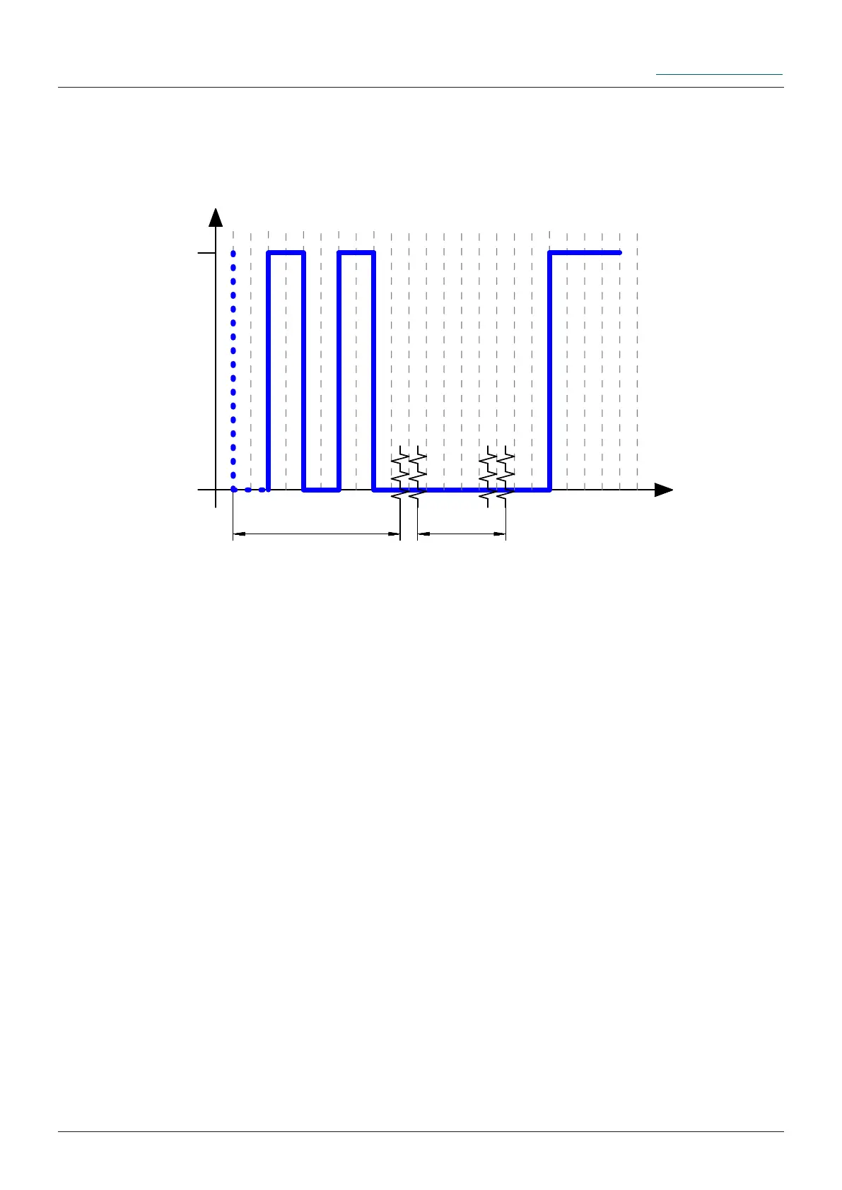
The transition of the output signals when changing a cartridge on the FlexxPump 125 in
the switched-on state is shown and described below:
U
24V
0V
t
PIN 4
E1 0,5 Hz E1 low
Z1
Z2
Description:
The FlexxPump 125 is properly connected to an external controller via the electrical
interface and connected to the power supply.
The Pulse-Control-Mode PUL is activated on the FlexxPump 125, E1 is displayed in
the LCD and the red LED lights up.
The empty state of the cartridge occurred after a donation, the output signal of the
FlexxPump 125 is initially the 0.5Hz square wave signal (empty state signal) (0/+24 V).
Z1 indicates the time of removal of the empty cartridge. The output signal of the
FlexxPump 125 now changes from a 0.5Hz square wave signal to a permanent low
signal (0V).
Z2 indicates the time for screwing on a new, full cartridge. The output signal of the
FlexxPump 125 now changes from a permanent low signal (0V) to a permanent high
signal (+24V). In this way the FlexxPump 125 signals to the external controller (PLC)
that it is ready for operation again.
If the empty state signal has occurred during the execution of the control signal 12 se-
conds, the outstanding strokes are continued after the new cartridge has been screwed
on.
The FlexxPump 125 does not process control signals until all errors have been
eliminated.
Z1: Removing the empty cartridge
Z2: Mounting the new cartridge