Do you have a question about the DLS FlexxPump 250 DLS and is the answer not in the manual?
Details the document's version changes and update log.
Provides contact and legal information for the manufacturer and service.
Defines the meaning of DANGER, WARNING, CAUTION, NOTICE, and INFORMATION signal words.
Illustrates and explains hazard symbols used in the manual.
Explains the systematic structure of safety instructions within the manual.
Details symbols used for action requests, consequences, and additional info.
Outlines compliance with relevant EC/EU directives for the machinery.
Identifies potential dangers to users and the machine during operation.
Specifies requirements and qualifications for personnel operating the equipment.
Defines improper uses that are considered prohibited and void warranty.
Details the specific industrial applications and conditions for correct product use.
Excludes warranty and liability for personal injury or property damage due to misuse.
Provides crucial safety guidelines for electrical connections and lubricant handling.
Explains the pump's design, operation, and integration with external controls.
Details the location and information found on the product's nameplate.
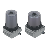
Describes the different versions of the product and included accessories.
Presents detailed technical specifications for housing, hydraulics, and electrics.
Instructions for handling and disposing of product packaging materials.
Advises against hard shocks to prevent damage during transport.
Specifies conditions for storing the product in a dry, frost-free environment.
Details the specifications for the FlexxPump 411 DLS and 211 DLS models.
Details the specifications for the FlexxPump 412 DLS and 212 DLS models.
Details the specifications for the FlexxPump 422 DLS and 222 DLS models.
Details the specifications for the FlexxPump 423 DLS and 223 DLS models.
Details the specifications for the FlexxPump 424 DLS and 224 DLS models.
Advises on preparing the installation site and reviewing safety instructions.
Step-by-step guide for assembling the pump unit and its components.
Steps for initial startup, including mechanical and electrical connections.
Key information for operating and setting up the FlexxPump with PLC control.
Details the M12x1 connector pinout and signal assignments for PLC communication.
Describes the control signals (input signals) from the PLC to the FlexxPump.
Explains the 2-second signal for a single dispensing process and its timing.
Explains the 5-second signal for dispensing operation on pump unit 2.
Details the 8-second signal for dispensing on pump units 1 and 2.
Describes the 12-second signal triggering the FIL function for 40 dispensing operations.
Explains the 14-second signal for acknowledging error messages.
Details the output signals from the FlexxPump to the PLC indicating status.
Describes the empty cartridge signal (E1) and its output on PIN 4.
Explains the 'Error Overload' signal (E2) indicating hydraulic overload.
Describes the 'Error Under- or Overvoltage' signal (E3) for power supply issues.
Details the 'Critical Error' signal (E4) indicating internal system malfunctions.
Provides a schedule for cleaning, visual checks, and cartridge changes.
Instructions for performing thorough visual inspections of the lubrication system.
Guidelines for cleaning the FlexxPump using suitable cleaning agents.
Steps for safely recommissioning the unit after maintenance procedures.
Detailed instructions on how to replace the lubricant cartridge.
Procedures for proper disposal of the FlexxPump and cartridges.
Lists approved lubricants and their designations found on cartridge labels.
Discusses considerations for installing the pump and tube length recommendations.
Provides detailed drawings with dimensions for installation and mounting.
Official declaration of compliance with relevant EC/EU directives for the product.
Illustrates the program flow for controlling the pump with a 2-second signal.
| Brand | DLS |
|---|---|
| Model | FlexxPump 250 DLS |
| Category | Lubrication systems |
| Language | English |