revision: 1
FlexxPump 250/400 DLS
User Manual
25
EN-
8. Input and output signals - External control (PLC)
For the electrical connection to an external control (PLC) of a system, the
FlexxPump 250/400 DLS has a 4-pin interface, which is designed as a plug connection
with the standard industrial M12x1 connection.
The FlexxPump 250/400 DLS can be switched off completely by switching off the
supply voltage. After reapplying the supply voltage, the FlexxPump 250/400 DLS
checks itself automatically but only operates after receiving an input signal from the
PLC.
To operate the FlexxPump 250/400 DLS via an external controller (PLC), a program
corresponding to the communication protocol must be created in the PLC. A basic
flowchart for the command of the FlexxPump 250/400 DLS can be found in the
appendix (chapter 11.4).
The output signal at PIN 4 can be tapped for further processing (e.g. indicator light
or external control). The maximum permissible output current must not exceed I
max
<
20mA. No inductive load (e.g. relay) may be connected!
After a longer standstill of the FlexxPump 250/400 DLS the manual execution of
the "Quick-Check" is recommended. You can use for example the 12 seconds control
signal to trigger a certain number of donations via the PLC (chapter 8.2).
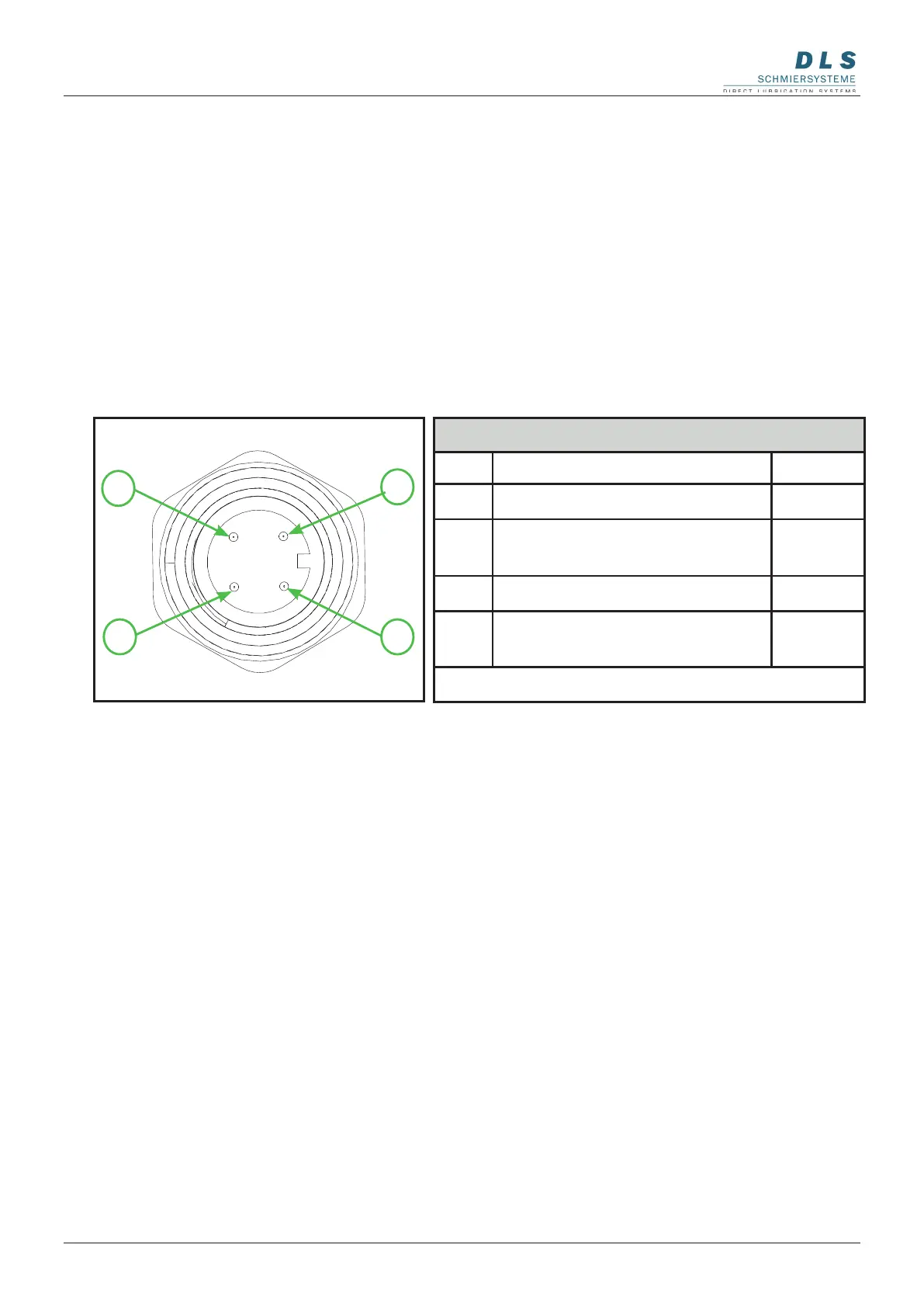
PIN-Assignment (PLC)
PIN Assignment Colour
1
+24 V DC
brown
2
Input Signal PLC
FlexxPump 400/200 DLS
white
3
Ground
blue
4
Output Signal FlexxPump
400/200 DLSPLC
black
Type: M12x1 female connector; 4-pin, A-coded
14
3
2
The FlexxPump 250/400 DLS operates as a pulse-controlled lubrication system only
if unalterable input signals (high level) are transmitted from the PLC to the Flexx-
Pump 250/400 DLS via PIN 2 in a dened sequence. The FlexxPump 250/400 DLS
signals the respective status to the PLC via high/low levels, which can be tapped off
at PIN 4, and thus enables comprehensive control or, by suitable programming of the
PLC, differentiated evaluation of the different statuses. For the integration of the Flexx-
Pump 250/400 DLS into an external control, one input and one output must be provided
on the control side.
8.1 Pin assignment - External control (PLC)