revision: 1
FlexxPump 250/400 DLS
User Manual
26
EN-
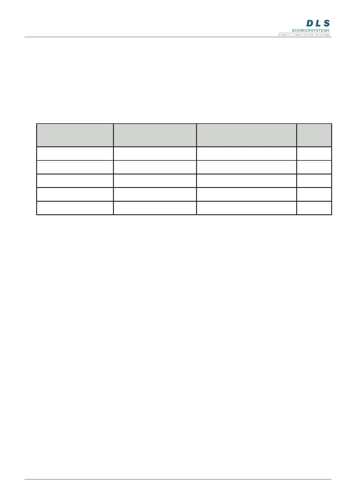
Signal length in
seconds
Description Function Detail
2 high
Signal 2 Seconds
1 Stroke PK1 8.2.1
5 high
Signal 5 Seconds 1 Stroke PK2 8.2.2
8 high
Signal 8 Seconds 1 Stroke PK1 and PK2 8.2.3
12 high
Signal 12 Seconds FIL-Function 8.2.4
14 high
Signal 14 Seconds Error acknowledgement 8.2.5
8.2 Input signals - External control (PLC)
The FlexxPump 250/400 DLS provides the following unalterably dened control signals
(input signals), which must be transmitted from the PLC to the FlexxPump 250/400 DLS
via PIN 2 of the electrical M12x1 interface as high level (+24 V DC).
The control signals must be generated as high level (+24 V) by the external controller
(PLC) over certain times with a tolerance of +/- 0.1 seconds.
The input signals that your FlexxPump 250/400 DLS can process depend on the
design of the FlexxPump 250/400 DLS. Compare your FlexxPump 250/400 DLS with
the different designs described in chapter 5 to nd out which signals are important for
your FlexxPump 250/400 DLS and can be used for control. The designation of your
FlexxPump 250/400 DLS can be found on the nameplate attached to the side of the
FlexxPump 250/400 DLS, see chapter 3.1, g. 1.
The FlexxPump 250/400 DLS only processes the control signals listed in the table
up to a maximum length of 14 seconds. If a high level (+24 V DC) is present outside
the tolerances, the FlexxPump 250/400 DLS does not react. If a high level (+24 V DC)
is applied to PIN 2 of the electrical interface for longer than 15 seconds, the LCD will
display --- and the FlexxPump 250/400 DLS will not react.