93010350.EN_A_Junior 4.0 User
Manual_240828_v1.0 - VVVF
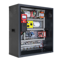
On mother board are present 6 leds for a easy diagnostic:
LED1: (Green led) not used.
LED2: (Green led) CAN Cabine termination active: led switch off when an optional board (PIT8 /
16IO / 16RL) is connected inside controller (termination automatically moves on last optional board).
LED3: (RGB led) color of this led gives info on the internal status of lift according following table:
The system is in temporary operations mode
The system is performing an emergency
procedure:
• Black out Automatic evacuation or
• Black out Manual evacuation or
• RNO operation
The system is in maintenance mode:
• Inspection from TOC or
• Inspection from PIT or
• PME rom Machine room
The system is performing the reset procedure
The system is out of service cause dby:
• the car drift control procedure or
• Water in Pit procedure
The system is operating an evacuation:
• Fire-fighters mode or
• Fire Evacuation or
• Tilt Evacuation (only for Ship)
The system is in priority mode:
• Priority call from LOP or
• Key Priority / VIP mode in the CAR
The system is parked from a key
• Lift Off Mode or
• Baggage Mode (Ship) or
• Shuttle mode (Ship)
The system is in normal operation mode
LED4: (Yellow led) led blinks when board is running.
LED5: (Green led) led on gives the status of SE5 safety chain
LED6: (Red led):
• Led OFF means no fault active.
• Led flashing means one (or more) fault active.
• Led ON means a locking fault active.
1.6.1. Controller power supply
Power supply from a commercial stabilized power supplier.
The negative terminal of the power circuits and the battery charger must be connected to the ground.