93010350.EN_A_Junior 4.0 User
Manual_240828_v1.0 - VVVF
The LSI on the power printed circuit board has malfunctioned
due to noise, etc.
CANopen communication error
A communications error has occurred during CANopen
communication.
EN1, EN2 terminals circuit error
An abnormality was diagnosed in EN1, EN2 terminals circuit.
Reference torque current became excessive.
Braking transistor broken
Detection of an abnormality in the brake transistor
The inverter detects mismatch between the brake control
signal and brake detection (feedback) signal.
EN1, EN2 terminals chattering
Detected collision between ENOFF output and EN1/EN2 terminals.
input
A customizable logic configuration error has caused an alarm.
Charging resistor overheat
The temperature of the charging resistor inside the has exceeded
the allowable limit. inverter
No movement detected during rescue operation by bra control. ke
Reaching maximum numbers of trip
counter
The number of trip direction changes has reached the preset
level.
Short-circuit control error
The inverter detects mismatch between the short-circuit
control signal and short-circuit detection (feedback) signal.
Load-cell function has detected overload situation by means
of preset level.
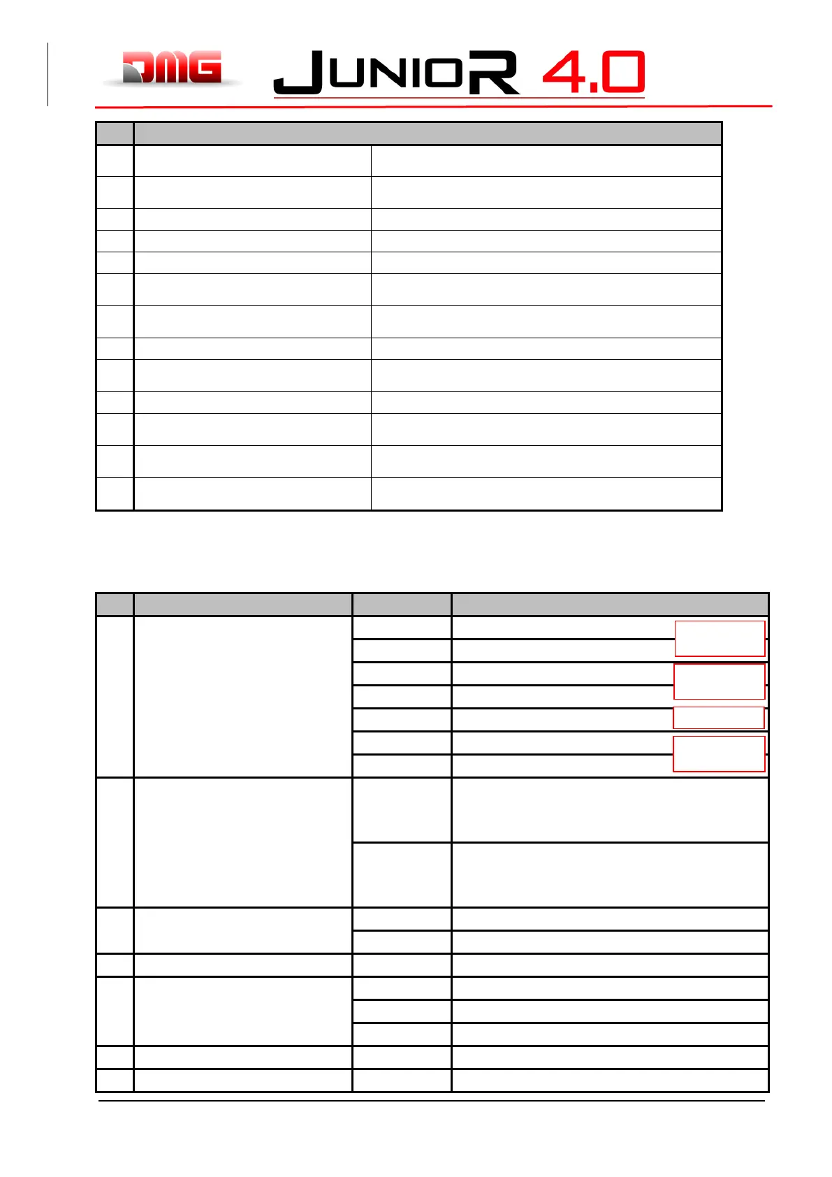
VVVF Alarm Sub code Table
Overcurrent protection (OCT interruption)
Overcurrent during acceleration
Overcurrent protection (OCL interruption)
Overcurrent during deceleration
Detection signal failure (FAULT signal)
Overcurrent during constant speed
Detection signal failure (OCT signal)
Detection signal failure (OCL signal)
Overvoltage during acceleration
Overvoltage Protection (OVT signal)
Overvoltage during deceleration
Overvoltage during constant speed
Detection signal failure (OVT signal)
Rectifier diode protection level detection
Continuous operation tolerance level detection
Cooling fin overheat (NTC2)
Converter overheat (NTC4)
Thermistor disconnection (NTC2)
Internal air overheat (NTC1)