Internal Clock power supply: Super Capacitor (autonomy of 5 days without power supply).
1.6.2. Encoder Position
Not used.
1.6.3. Relevelling Circuit
Circuit to make Door Safety Contact Bypass for:
• Pre opening and/or
• Relevelling
The circuit management of the re-leveling operation consists of two Safety Relays.
• ISO output (safety relay contact) open collector Max 24V 100mA
• Input CCISO (Monitor ISO safety relay) closure to GND (NC) I = 5mA
• Input TISO (Monitor Safty module) closure to GND (NC) I = 5mA
1.6.4. Optional Board
Not used.
1.6.5. Emergency Circuit
Circuit for complete Emergency or Evacuation with Brake opening.
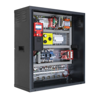
1.6.6. PME Panel
Connection to the Control Panel inside the cabinet.
1.6.7. Parallel Signal
Connection to the APPO Board. It includes all parallel signals available on the Cabinet’s screw terminal.
1.6.8. UCM Circuit
Connection to the circuit for UCM solution. Junior 4.0 has own certified solutions for managing of UCM
solution in lift installations.
The UCM system consists of three parts:
• Detector who detects an Unintended Cabine Movement.
• Actuator how the braking action is implemented
• Stopping Device what stops the cabin.
The Stopping Device must be a certified safety device and it is the installer's responsibility to ensure
the compatibility of the different elements of the UCM system.
For the functional verification of the entire system and the measurement of the spaces and intervention
times, specific tests are provided to be carried out at the end of the assembly (see Appendix II).
For further information on connections and parameters see ANNEX VIII
A non-exhaustive list of the types of UCM systems and solutions most used are shown in the following
table, where different applicable solutions are highlighted, each of which has its own dedicated
interface and programming circuit. The interfacing with the listed devices is carried out according to the
specifications indicated in the manuals of the relevant manufacturers.
When the absolute positioning system ELGO LIMAX 33CP is provided (§7), its certified UCM function is
used.