1835-065-D-5-17
8
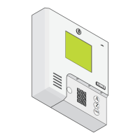
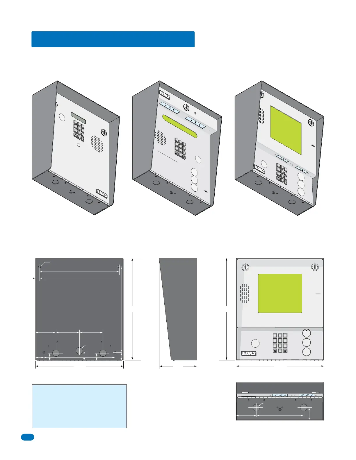
1.2 Surface Mount Dimensions
Surface mount units can be mounted directly to a wall, pilaster, post mounted using a DoorKing architectural style mounting
post (P/N 1200-037 and 1200-038) or recessed in a wall (see next page) with the surface mount recess kit (P/N 1803-150). Be
sure the unit is mounted securely and is not subject to vibration from closing doors or gates.
13” 13”
11.25”11.25”
4.75”
Bottom View
Side ViewBack View Front View
7
8
9
4
5
6
1
2
3
0
OPER
WXYZ
TUV
PQRS
MNO
JKL
GHI
DEF
ABC
SP
CALL
Z
A
A
Z
CALL
7
8
9
4
5
6
1
2
3
0
O
PE
R
WXYZ
T
U
V
PQ
RS
MN
O
JK
L
G
HI
DEF
ABC
SP
T
ELEPHONE ENTRY SYS
T
EM
HOLD TO
SCAN
OPERATING INST
RUCTIONS
Us
e
“A to Z”
Bu
t
t
o
n
s
t
o
L
o
ca
t
e
Name and C
o
de
N
um
ber on D
is
play
.
Na
mes
a
re In
Alph
abe
ti
ca
l Or
d
er.
To
C
a
ll,
Ent
er
C
ode Nu
m
ber on
Keypad or
P
ress
“Call” Button. If
L
i
n
e is Busy
,
Pr
ess
“
#”
o
r
“
C
a
ll”
t
o
Ha
ng Up.
Tr
y Ag
ain
.
Ent
er
o
n Open Di
spla
y
a
nd
To
n
e.
1
.
2.
3
.
A
Z
CALL
7
8
9
4
5
6
1
2
3
0
OPE
R
WXYZ
T
U
V
PQRS
M
N
O
J
KL
G
H
I
D
EF
ABC
SP
7
8
9
4
5
6
1
2
3
0
O
PE
R
W
X
Y
Z
TUV
PQRS
MN
O
JK
L
G
H
I
D
EF
ABC
SP
T
ELEPHONE ENTR
Y S
YST
E
M
OP
E
RAT
IN
G
INSTRUCTIONS
L
ocate Cod
e
Nu
mb
er
on
D
irecto
ry
.
P
ress
C
o
de
Numbe
r
. If L
ine
is
Busy
,
P
ress
“#”
to
H
a
ng
UP
.
Tr
y
Agai
n
.
E
nte
r
on
Ton
e
.
1.
2.
3.
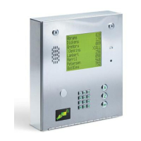
1835
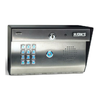
1837
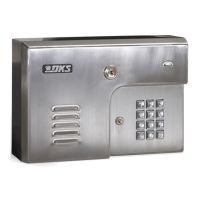
1833
10.125”
.5”
2.625” 3”
1”
.875”
1.25”
.875”
10.875”
1.125”
9”
3”
.25” Dia. Mounting Hole
.875” Dia
.875” Dia
6”
1.625”
2.625”
WARNING! If this entry system is used to
control a vehicular gate with an automatic gate
operator, the entry system must be mounted a
minimum of six (6) feet away from the gate and
gate operator, or in such a way that a person
cannot operate the entry system and touch the
gate or gate operator at the same time.
DoorKing recommends replacing the Standard Key Lock with the “Random” Key Lock that is included. See back cover for more information.
 Loading...