1835-065-D-5-17
18
The use of surge suppressors can significantly reduce the chance of component failure because of static charges or surges.
DoorKing recommends Installing a Phone Line surge suppressor (DoorKing P/N 1877-010 or equivalent) and a Low Voltage
surge suppressor (DoorKing P/N 1878-010 or equivalent) to help protect the entry system from power surges.
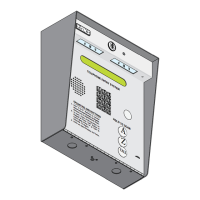
Proper grounding of this system is a requirement. To be effective, ground connections should be made with a minimum 12
AWG, 600 volt insulated wire to a ground point within 10 feet of the telephone entry system. The ground point must be at an
electrical panel, a metallic cold water pipe that runs in the earth, or a stainless steel grounding rod driven at least ten (10) feet
into the soil. A architectural style mounting post anchored to concrete does NOT make a good ground.
Install on each
16.5 VAC Transformer
Surge suppressor within 3 ft of ground source.
POWER LINE
1878-010
Low voltage surge suppressor
within 10 ft of entry system.
CALL
Z
A
Some Acceptable Ground Sources
Ground to a metallic cold water pipe.
Ground
Wire
Ground
Wire
Ground to an existing electrical system.
Electrical
Panel
Grounding rod 10 feet in soil.
IMPORTANT: Ground wire shown without
safety protection for clarity. Make sure
ground wire is protected from being
touched or electrical shock could occur!
Phone line surge suppressor
within 10 ft of entry system.
CALL
Z
A
Surge suppressor within 3 ft of ground source.
Phone Company
PHONE LINE
1877-010
2.1.3 Grounding
2.1.4 Surge Suppression
2.1.5 Expansion Boards and Elevator Control
2.1.6 Ferrite Filter
I
f Expansion Boards are being used with this system, refer to the Installation and Wiring manual that came with the Expansion
boards, for detailed information on wiring Expansion boards to the PC programmable telephone entry system.
If Elevator Control is used with this system, refer to the Elevator Control Installation and Wiring manual for detailed information
on wiring the elevator control boards to this system and to the elevator push button control panel.
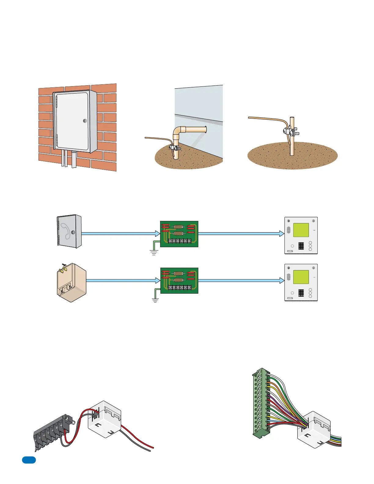
The Telephone Entry System comes with two (2) Ferrite Filters. These will help
prevent noise and hum pickup in the phone lines. One is installed around the 16 VAC
power wires on the main terminal #19 and #20. The second is installed around all the
wires connected to the aux terminal.
To install the ferrite filter, release the
clip on the side to open the filter,
place the wires in the circular core
and snap the filter closed.
Power Wires
on all models
Auxiliary Wires
1
6AC
20
19
18
1
7
16
15
14
1
6AC
Main Terminal
Aux Terminal
BA
T
1
N
O
1N
C
2RY
2C
14
12
13
11
10
9
8
7
6
5
4
3
2
1
Clip Release
Clip Release
#1
#2
Phone Line Surge Suppressor
Low Voltage Surge Suppressor
 Loading...