1835-065-D-5-17
21
34
33
32
31
30
29
28
27
26
25
24
23
22
21
14
15
16
17
18
19
20
13
12
11
10
9
8
7
6
5
4
3
2
1
ON
1
0
BOARD ADDRESS
0
9
8
7
6
5
4
3
2
1
NC
OUTPUT
RELAY
NO
NC
ALARM
RELAY
NO
NC
AUX
RELAY
NO
ENT
RESET
2358-010
RF
DATA
RF
SECURE
RF
STATUS
CODE
SENT
CODE
GOOD
CODE
BAD
34
33
32
31
30
29
28
27
26
25
24
23
22
21
14
15
16
17
18
19
20
13
12
11
10
9
8
7
6
5
4
3
2
1
ON
1
0
BOARD ADDRESS
0
9
8
7
6
5
4
3
2
1
NC
OUTPUT
RELAY
NO
NC
ALARM
RELAY
NO
NC
AUX
RELAY
NO
ENT
RESET
2358-010
RF
DATA
RF
SECURE
RF
STATUS
CODE
SENT
CODE
GOOD
CODE
BAD
NC
NO
ELEVATOR
16AC16ACBAT1NO1NC1C2RY2CA
1
2
3
Auxiliary Terminal
NO NC C
Brown
Blue
Blue
to 1NO
Brown
to 1C
Lock Power
UL listed
Board Power
UL listed
#33 & #34
Board Power
UL listed
#33 & #34
16 VAC
20 VA
Lock Power
UL listed
Wiegand Card Reader
#6 - #9
Wiegand Card Reader
#6 - #9
16 VAC
20 VA
Ground #32
Ground #32
Blue #17
Red #10
Brown #19
Blue #17
Red #10
Brown #19
Black #27
White #28
Green #29
Black #27
White #28
Green #29
12345678910 1112 13 14
First 1 to 12 Boards Board Addresses 3-10
Door Lock
or Gate
Operator
#25 & #26
Door Lock
or Gate
Operator
#25 & #26
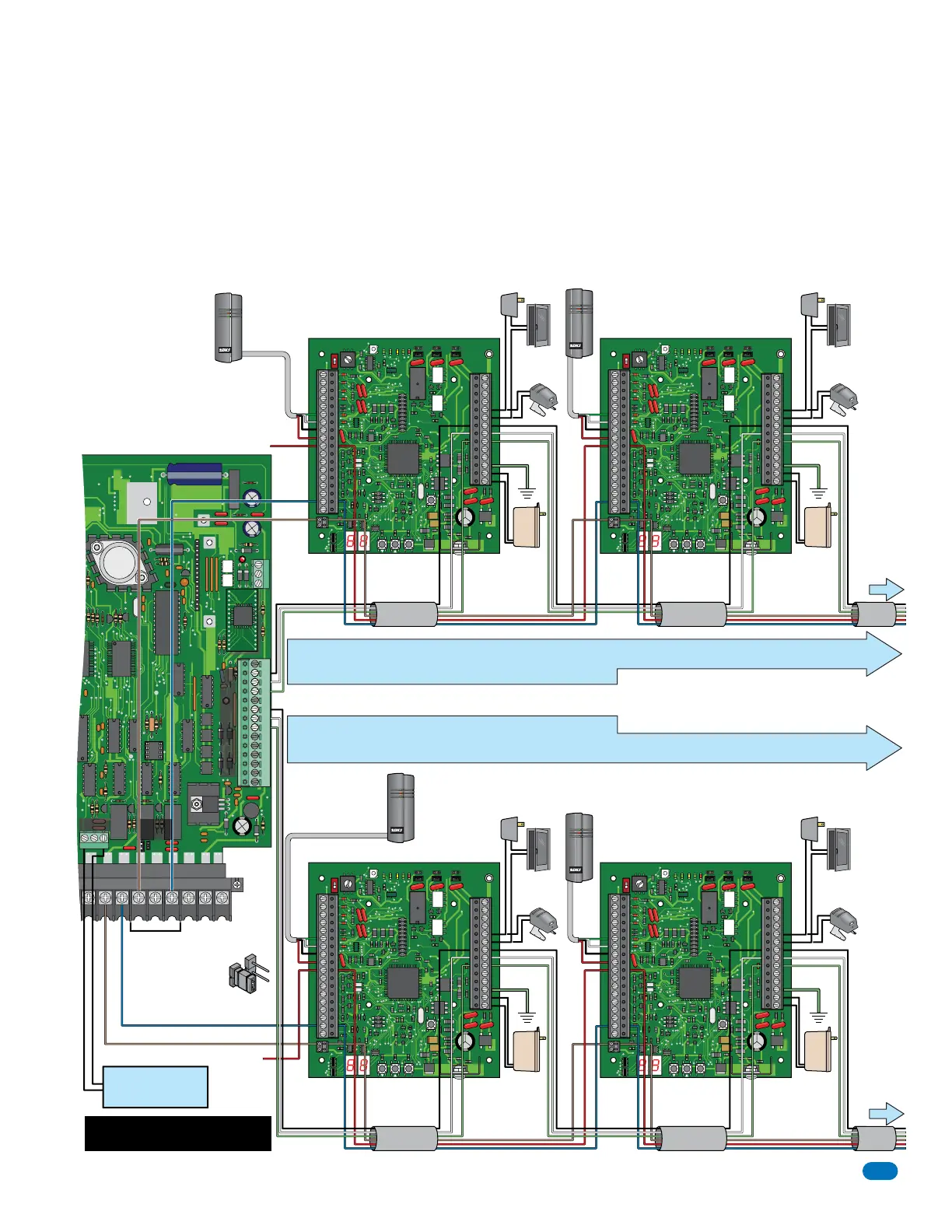
• The farthest board can be NO more than 2000 ft from the telephone entry system.
• Do not use twisted pair wire with 26, 30 and 31-Bit wiegand output format.
• Proper grounding is required! Ground wire should be a minimum 12 AWG.
8 board addresses available per Aux terminal.
12 tracker boards Max per Aux terminal using zone addresses.
Next 13 to 24 Boards Board Addresses 11-18
• The farthest board can be NO more than 2000 ft from the telephone entry system.
• Do not use twisted pair wire with 26, 30 and 31-Bit wiegand output format.
• Proper grounding is required! Ground wire should be a minimum 12 AWG.
34
33
32
31
30
29
28
27
26
25
24
23
22
21
14
15
16
17
18
19
20
13
12
11
10
9
8
7
6
5
4
3
2
1
ON
1
0
BOARD ADDRESS
0
9
8
7
6
5
4
3
2
1
NC
OUTPUT
RELAY
NO
NC
ALARM
RELAY
NO
NC
AUX
RELAY
NO
ENT
RESET
2358-010
RF
DATA
RF
SECURE
RF
STATUS
CODE
SENT
CODE
GOOD
CODE
BAD
34
33
32
31
30
29
28
27
26
25
24
23
22
21
14
15
16
17
18
19
20
13
12
11
10
9
8
7
6
5
4
3
2
1
ON
1
0
BOARD ADDRESS
0
9
8
7
6
5
4
3
2
1
NC
OUTPUT
RELAY
NO
NC
ALARM
RELAY
NO
NC
AUX
RELAY
NO
ENT
RESET
2358-010
RF
DATA
RF
SECURE
RF
STATUS
CODE
SENT
CODE
GOOD
CODE
BAD
Lock Power
UL listed
Board Power
UL listed
#33 & #34
Board Power
UL listed
#33 & #34
16 VAC
20 VA
Lock Power
UL listed
Wiegand Card Reader
#6 - #9
Wiegand Card Reader
#6 - #9
16 VAC
20 VA
Ground #32
Ground #32
Blue #17
Red #10
Brown #19
Blue #17
Red #10
Brown #19
Black #27
White #28
Green #29
Black #27
White #28
Green #29
Door Lock
or Gate
Operator
#25 & #26
Door Lock
or Gate
Operator
#25 & #26
Relay 0
Main Door/Gate
IMPORTANT NOTE: ONLY use circuit
board 2358-010 Rev L or higher.
The model 2358 Tracker Expansion Board (sold separately) allows you to expand the number of remote entry points that the
telephone entry system can control. One tracker expansion board is required for EACH remote entry point. Up to 24 boards can
be hardwired to the circuit board’s Aux Terminal (First 12 boards connected to #7 - #9 and 12 more boards connected to #11 -
#13 if needed). Tracker expansion boards must have their own power source and the farthest board can be no more than 2000
ft from the telephone entry system. Each board must have a board address set on it to identify it to the telephone entry system
and if wiring more than 8 boards, some zone addresses need to be used for identification. The tracker expansion boards are
pre-programmed with many features but can be re-programmed for specific needs when desired. See Tracker Expansion Board
Manual 2358-065 for ALL wiring and programming options.
2.3.2 Tracker Expansion Boards (Hardwired)
Main Terminal
Connect card reader using
4 conductor, stranded with
overall shield.
18, 20, 22 or 24 gauge.
Relay 2
“2RY” Contact is
set NO with Relay
2 Jumper on board.
Relay 1
Wire to 1C/1NO
Red - NO circuit board connection.
Red - NO circuit board connection.
Aux Terminal #7 - #9
Aux Terminal #11 - #13
Board Address 3 Board Address 4
Relay 2
Jumper
Relay 0
Telephone
Entry
System
Circuit
Board
NC
NO
To Board
Addresses
5 thru 10
Zone Addresses
must be used
when more than 8
boards are wired,
12 boards MAX.
Connect card reader
using 4 conductor,
stranded with overall
shield. 18, 20, 22 or
24 gauge.
Board Address 11 Board Address 12
To Board
Addresses
11 thru 18
Zone Addresses
must be used
when more than 8
boards are wired,
12 boards MAX.
Tracker Expansion Board Power: You may power up to four (4)
expansion boards from a single 16 VAC, 50 VA power transformer.
18 AWG wire up to 100 Ft.
16 AWG wire up to 200 Ft.
It is advisable to keep power wire runs as short as possible.
Hardwire tracker expansion boards using 6 conductor, stranded with
overall shield. 18, 20, 22 or 24 gauge. Shield runs continuous. Float the
shield, DO NOT connect shield to 2358-010 board common.
 Loading...