VigorSwitch G2080 User’s Guide
11
1
1
.
.
5
5
.
.
5
5
C
C
o
o
n
n
f
f
i
i
g
g
u
u
r
r
i
i
n
n
g
g
t
t
h
h
e
e
M
M
a
a
n
n
a
a
g
g
e
e
m
m
e
e
n
n
t
t
A
A
g
g
e
e
n
n
t
t
o
o
f
f
S
S
w
w
i
i
t
t
c
c
h
h
We offer you three ways to startup the switch management function. They are RS-232
console, CLI, and Web. Users can use any one of them to monitor and configure the switch.
You can touch them through the following procedures.
Section 2-1-4-1: Configuring the Management Agent of VigorSwitch G2080 through the
Serial RS-232 Port
Section 2-1-4-2: Configuring the Management Agent of VigorSwitch G2080 through the
Ethernet Port
Note: Please first modify the IP address, Subnet mask, Default gateway and DNS
through RS-232 console, and then do the next.
Configuring the Management Agent of VigorSwitch G2080 through the Serial RS-232
Port
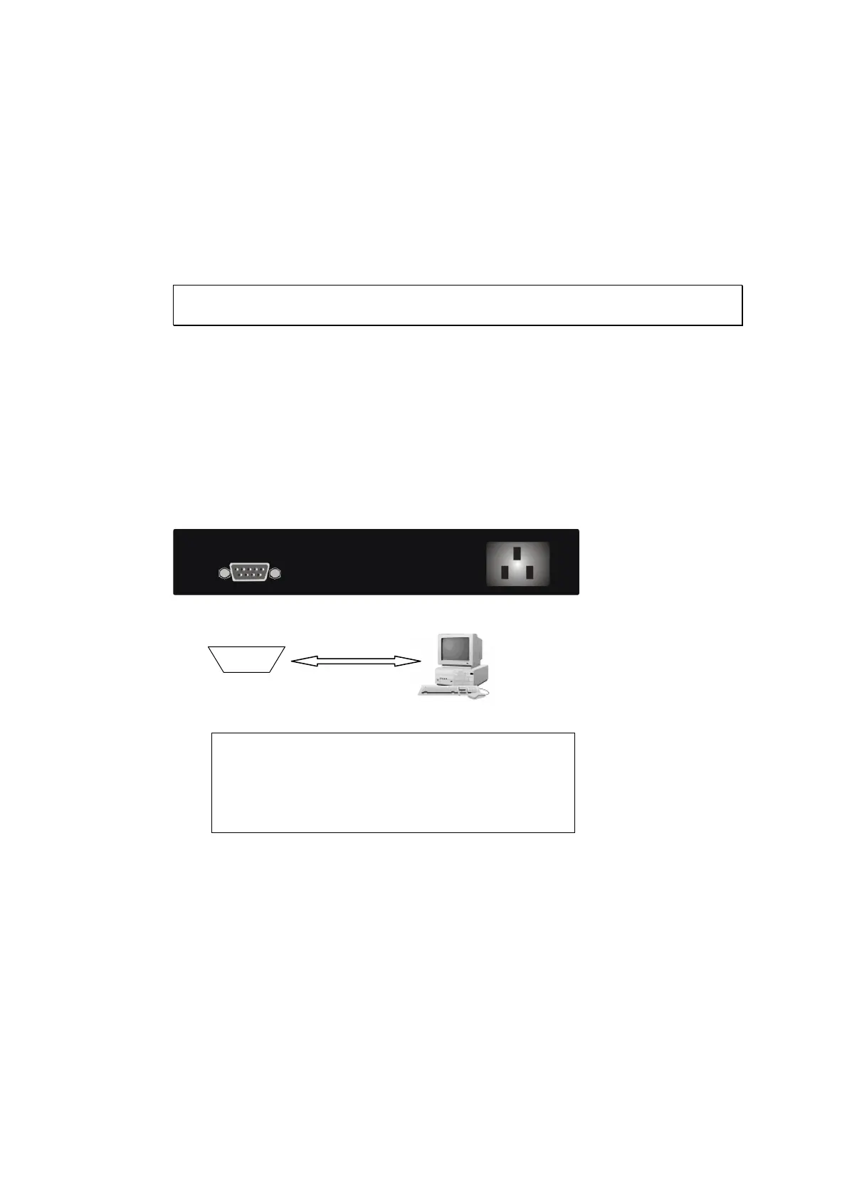
To perform the configuration through RS-232 console port, the switch’s serial port must be
directly connected to a DCE device, for example, a PC, through RS-232 cable with DB-9
connector. Next, run a terminal emulator with the default setting of the switch’s serial port.
With this, you can communicate with the switch.
In the switch, RS-232 interface only supports baud rate 57.6k bps with 8 data bits, 1 stop
bit, no parity check and no flow control.
RS-232 cable with female DB-9 connector at both ends
VigorSwitch G2080
Default IP Setting:
IP address = 192.168.1.1
Subnet Mask = 255.255.255.0
Default Gateway = 192.168.1.254
To configure the switch, please follow the procedures below:
1. Find the RS-232 DB-9 cable with female DB-9 connector bundled. Normally, it just
uses pins 2, 3 and 7. See also Appendix B for more details on Null Modem Cable
Specifications.
2. Attaches the DB-9 female cable connector to the male serial RS-232 DB-9 connector
on the switch.
3. Attaches the other end of the serial RS-232 DB-9 cable to PC’s serial port, running a
terminal emulator supporting VT100/ANSI terminal with the switch’s serial port
default settings. For example, Windows98/2000/XP HyperTerminal utility.
RS-232
 Loading...